Introduction
Injection mold tool design is the foundation of every successful plastic part. Engineers and procurement managers know that poor tooling decisions cascade into defects, cost overruns, and production delays, while well-designed tooling delivers consistent quality at scale. According to recent industry data, approximately 50% of injection molding defects stem from inadequate mold design rather than process parameters—meaning your mold design, not your process settings, is the primary driver of part quality.
This guide covers the critical decisions engineers face when designing injection mold tooling: mold configuration types, DFM principles, material selection, and cost drivers. Whether you're prototyping a consumer product or launching high-volume automotive components, the goal is the same — get the tool design right before production starts.
TLDR
- Mold design defines every structural and geometric feature that determines whether plastic fills, cools, and ejects without defects
- Key parameters include uniform wall thickness, draft angles, rib/boss sizing, parting line placement, and gate location
- Match mold type (single-cavity, multi-cavity, family, or insert) to your production volume and part complexity
- Tooling material (P20, H13 steel, or aluminum) affects mold lifespan, surface finish, and upfront cost
- Getting DFM right early prevents expensive post-fabrication rework
Types of Injection Molds and When to Use Each
Selecting the right mold configuration before investing in tooling is critical—the wrong choice inflates per-unit cost or limits production flexibility. Production volume, part complexity, and design maturity determine which mold architecture best fits your program.
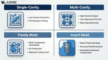
Single-Cavity Molds
Single-cavity molds produce one part per cycle, making them ideal for prototyping, low-volume runs, or highly complex geometries requiring individual attention. Upfront tooling investment is lower—aluminum single-cavity molds typically range from $2,000 to $5,000—but cost-per-part remains higher at scale since you produce only one part per cycle.
Use single-cavity molds when:
- Your design is still evolving or undergoing iteration
- Annual demand stays below 10,000 units
- Part complexity (deep draws, tight tolerances, intricate surface details) makes multi-cavity balancing impractical
Multi-Cavity Molds
Multi-cavity molds produce multiple identical parts per cycle, dramatically reducing cycle time and cost-per-unit. Industry benchmarks indicate that annual part demand exceeding 100,000 units with stable product design justifies multi-cavity tooling investment. Per-part costs drop sharply at scale: from approximately $4.00 at 100 parts to $1.70 at 100,000 parts as tooling amortization spreads across higher volumes.
Multi-cavity tooling costs more upfront. Steel production molds range from $5,000 to over $100,000 depending on cavity count and complexity, but the economics make sense for mature designs with predictable long-term demand.
Family Molds
Family molds produce different parts or part variants in a single mold base, making them valuable for product assemblies, kits, or component sets that ship together. Runner balancing is the critical design challenge here. Unbalanced runners can require up to 50% higher injection pressure and cause non-uniform shrinkage, flash, and sink marks across different cavities.
The underlying physics explains why this is hard to fix after the fact: pressure drop is proportional to runner length divided by the fourth power of runner radius, meaning small diameter changes have outsized effects on flow balance. Running a Moldflow Runner Balance Analysis before cutting steel is the most reliable way to catch these issues early.
Insert Molds
Insert molds incorporate pre-placed metal or non-plastic components into the molded part during the injection cycle, bonding metal inserts (brass, steel, stainless steel threaded fasteners) within the plastic in a single operation. This eliminates secondary assembly steps for threaded inserts, metal reinforcements, electrical contacts, and mounting brackets.
Insert molding is common in automotive (electrical connectors, dashboard components, fasteners), electronics (plugs, sockets, surface mount pads), and medical devices (surgical tool handles, device housings).
Key Design Principles for Injection Molding Tool Design
These DFM (Design for Manufacturability) rules prevent costly defects and mold rework. Decisions made at the CAD stage directly determine tooling cost, cycle time, and part quality — fixing design errors after tool fabrication begins is expensive and slow.
Wall Thickness
Uniform wall thickness is the single most important design rule. Inconsistent walls cool at different rates, causing warping, sink marks, and voids. Recommended wall thickness varies by resin:
| Resin | Recommended Wall Thickness (mm) |
|---|---|
| ABS | 1.14 - 3.56 |
| PP (Polypropylene) | 0.64 - 3.81 |
| PC (Polycarbonate) | 1.02 - 3.81 |
| Nylon (PA) | 0.76 - 2.92 |
| HDPE | 0.76 - 5.08 |
| POM (Acetal) | 0.76 - 3.05 |
Walls too thick increase material use and cycle time, raising cost. Walls too thin risk incomplete fill (short shots). Transitions between different thicknesses should be gradual using chamfers or fillets, with adjacent walls at 40-60% of nominal wall thickness to prevent sink marks.
Draft Angles
Draft angles (tapered vertical walls) allow parts to release cleanly from the mold after cooling. General rules: 1-2 degrees for smooth surfaces, 3 degrees minimum for shutoffs and light textures, and 5 degrees or more for heavy textures like leathery or heavily grained finishes. Insufficient draft leads to drag marks, sticking, and accelerated mold wear. Specify surface finish before tool design to lock draft angles early.
Ribs, Bosses, and Structural Features
Rib design rules:
- Rib thickness should be 50-60% of nominal wall thickness (reduced to 40% for glossy materials to prevent visible sink marks)
- Maximum rib height-to-thickness ratio of 3:1
- Rib spacing of 2.5 to 3 times nominal wall thickness
- Base radii of 0.5 to 1 times part wall thickness
Boss design rules:
- Boss wall thickness approximately 60% of nominal wall thickness
- Boss height less than 3 times outer diameter
- Base radius of 0.25 to 0.5 times nominal wall thickness
- Minimum draft of 0.5 degrees on OD and 0.25 degrees on ID
- Standalone bosses should connect to nearest side wall for rigidity
Parting Lines, Gates, and Ejector Pins
Parting line: Place at sharp edges or transitions to minimize visual impact and reduce flash risk. The parting line is where the two mold halves meet; poor placement creates visible seams on cosmetic surfaces.
Gate location: Affects fill pattern, weld lines, and surface cosmetics. Gates should be placed at the thickest cross-section.
In fiber-filled materials, strength reduction at weld lines can reach 50-60% compared to non-weld areas. Run fill simulation and relocate gates to push weld lines away from structural and cosmetic surfaces.
Ejector pins: Target strong, non-cosmetic surfaces with distributed force to prevent deformation. Avoid placing ejector pins on visible surfaces or thin-walled areas prone to warping.
Undercuts and Side Actions
Features not in the mold's line of draw—undercuts, side holes, snap-fit clips—require side actions (slides, lifters) or hand-load inserts to release the part. These add significant tooling complexity and cost. Minimize or redesign undercuts during early DFM review where possible. When side actions are unavoidable, ensure adequate space in the mold base and account for increased maintenance requirements.
Tooling Materials: Choosing the Right Material for Your Mold
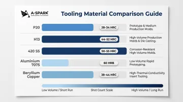
Mold material selection comes down to three variables: production volume, resin type, and budget. Harder steels handle abrasive materials and high shot counts; softer or lighter options reduce upfront cost and lead time for lower-volume programs. The table below maps each material to its practical range.
Tooling material options:
| Material | Hardness (HRC) | Approximate Shot Count | Typical Application |
|---|---|---|---|
| P20 (pre-hardened) | 28-32 | 50,000-100,000 | General-purpose; ABS, PP, PE |
| H13 (hardened) | 48-52 | 500,000-1,000,000+ | High-volume; glass-filled nylon; abrasive resins |
| 420 SS (stainless) | 48-52 | 500,000-1,000,000+ | Medical, optical, food-grade; corrosive resins like PVC |
| Aluminium (7075) | N/A | Low volume (thousands) | Prototype and bridge tooling; non-abrasive resins |
| Beryllium Copper | N/A | High-volume inserts | Core inserts for fast heat transfer and cycle time reduction |
When to choose each material:
- P20 machines at 65-75% of baseline steel rate — use it for SPI Class 103-104 programs with commodity resins (ABS, PP, PE) under 100,000 shots
- H13 machines slower (45% of baseline) but resists wear against abrasive resins like glass-filled nylon; required for SPI Class 101-102 molds exceeding 500,000 cycles
- 420 SS provides corrosion resistance for medical, food-grade, and optical parts — the right call when molding PVC or when mold sanitation is a requirement
- Aluminum (7075) machines fast and dissipates heat well, making it practical for prototype and bridge tooling under 60,000 shots; avoid it for abrasive resins or high-volume runs
- Beryllium copper is reserved for core inserts where rapid heat extraction is the priority — it reduces cycle time in high-volume commodity plastic applications (PP, PE families)
Key Factors That Influence Injection Molding Tool Design Decisions
Three variables drive nearly every consequential decision in mold design: what the part looks like, what material it's made from, and how many parts you need to produce.
Part Geometry and Complexity
Deep draws, thin walls, fine surface details, and tight tolerances all require more sophisticated — and more expensive — mold features. Simplifying geometry in early design stages delivers measurable tooling savings before a single dollar is spent on steel.
Key geometry factors that add cost and lead time:
- Undercuts: Each one requires a side action (slide or lifter), adding mechanical complexity
- Tight tolerances: Often demand hardened tool steel and extended qualification cycles
- Cosmetic surface requirements: Textured or polished cavities require additional processing and careful gate placement to avoid visible flow marks
Resin Properties and Material Selection
Different resins behave differently inside a mold — shrink rates, flow properties, and processing temperatures all affect cavity sizing, gate dimensions, cooling channel layout, and steel selection.
Shrink rates vary widely: PC runs 0.5–0.8%, while HDPE can reach 1.5–4.0%. The resin family matters here:
- Semi-crystalline resins (PP, PA66, HDPE, POM): Higher and more variable shrinkage; require tighter mold tolerance control and wider dimensional tolerance bands on the part
- Amorphous resins (ABS, PC): More predictable shrinkage and generally easier to tool for
- Glass-fiber reinforcement: Reduces overall shrinkage but introduces directional (anisotropic) shrinkage behavior and accelerates mold wear — both must be factored into cavity design
Production Volume
Volume determines the right tool class. For prototyping or low runs, aluminum single-cavity molds are often sufficient. For high-volume automotive or consumer electronics production, hardened steel multi-cavity tools are the appropriate long-term investment.
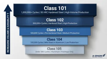
The SPI mold classification system provides a practical framework:
| Class | Cycle Life | Cavity Steel | Typical Use |
|---|---|---|---|
| 101 | 1M+ cycles | 50 HRC hardened | High-volume production |
| 102 | 500K–1M cycles | Hardened steel | Medium-high volume |
| 103 | Up to 500K cycles | Pre-hardened steel | Medium volume |
| 104 | Up to 100K cycles | Mild steel or aluminum | Low volume |
| 105 | Under 500 cycles | Aluminum | Prototype only |
Choosing a tool class below your actual production needs is one of the most common — and costly — tooling mistakes.
The Injection Mold Tool Design Process: From Concept to Production
The four-stage process: design and DFM → tool fabrication → assembly and inspection → sampling. Decisions made in Stage 1 determine the cost and timeline of all subsequent stages.
Design and DFM Analysis
The process begins with translating part requirements into a mold design using CAD/CAM software. DFM analysis flags potential issues — wall thickness violations, insufficient draft, problematic gate locations, undercuts — before any steel is cut. Changes at this stage cost hours; post-fabrication changes cost days and significant money.
Moldflow simulation predicts fill patterns, weld line locations, cooling efficiency, and potential defects, allowing engineers to optimize gate placement, runner sizing, and cooling channel layout before committing to fabrication.
Tool Fabrication and Assembly
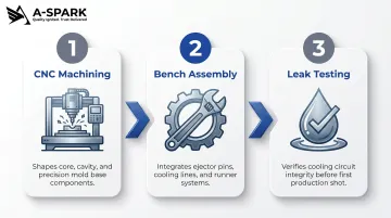
Once the design is validated, fabrication follows a structured sequence:
- CNC machining shapes the core, cavity, and mold base from the selected tooling material
- Bench assembly integrates ejector pins, cooling lines, and runner systems
- Leak testing verifies cooling circuit integrity before the first shot
A-SPARK's in-house tooling workshop and CNC machining capabilities—combined with fast design analysis and short prototyping cycles—allow customers to compress this stage and accelerate time-to-market. With tooling lead times typically ranging from 4 to 6 weeks depending on part complexity, A-SPARK's Vietnam-based engineering team provides rapid tooling options for urgent projects under IATF 16949-certified quality controls.
Sample Parts and Production Approval
T1 (first article) sample parts are produced and measured against dimensional tolerances, surface finish specifications, and functional requirements. If adjustments are required, engineering change orders are submitted before full production begins. The PPAP (Production Part Approval Process) comprises 18 elements across 5 submission levels, with T1 mould trial samples forming the dimensional and cosmetic baseline. Skipping or compressing T1 validation under schedule pressure risks field quality issues and downstream PPAP failures — a recoverable problem at the sample stage becomes a costly one in production.
How Much Does Injection Mold Tooling Cost?
Primary cost drivers: Part complexity and size, number of cavities, tooling material, surface finish requirements, and the need for side actions or hot runner systems.
Indicative cost ranges:
- Aluminium prototype mould (single-cavity): $2,000 – $5,000
- Steel production mould (single-cavity, mid-complexity): $5,000 – $100,000
- Complex multi-cavity hardened steel mould: $100,000+
Hot runner systems add roughly 25% to mould cost upfront, but the trade-off is significant: cold runner waste can account for up to 18% of total production cost, while hot runner systems eliminate runner scrap entirely. Whether the switch makes financial sense depends on resin cost, runner volume, and annual production volume.
From a total cost of ownership standpoint, hardened steel tooling pays back over large production volumes through lower per-part cost and longer mould life. Aluminium tooling, on the other hand, is the right call when the design is still evolving or volumes stay below 10,000 units.
For global OEMs sourcing tooling from Vietnam, labour and overhead cost structures in the region can shift these ranges meaningfully downward compared to Western markets. A-SPARK's engineering team, backed by IATF 16949-certified manufacturing partners, provides DFM analysis early in the quoting process — helping customers choose the right tooling specification before costs are locked in.
Frequently Asked Questions
How do you design for injection moulding?
Designing for injection moulding means applying DFM principles: uniform wall thickness, draft angles of 1-2 degrees minimum, and properly sized ribs and bosses (50-60% of wall thickness). Strategic gate placement and smooth feature transitions ensure the part fills, cools, and ejects cleanly without defects.
How much does a custom injection mould cost?
Costs vary widely based on part complexity, number of cavities, and tooling material. Aluminium prototype tooling typically ranges from $2,000 to $5,000, while hardened steel production moulds range from $5,000 to over $100,000 depending on cavity count, side actions, and surface finish requirements.
What is the difference between single-cavity and multi-cavity injection moulds?
Single-cavity moulds produce one part per cycle and suit low-volume or complex parts where upfront tooling cost is the priority. Multi-cavity moulds produce several identical parts per cycle, reducing cost-per-part at higher volumes — typically above 100,000 units annually — where amortisation across more units justifies the higher tooling investment.
What are the most common injection moulding defects caused by poor tool design?
The most common defects traced to mould design rather than process parameters include:
- Sink marks — caused by thick walls or oversized ribs
- Warping — from non-uniform cooling or inconsistent wall thickness
- Short shots — from undersized gates or inadequate venting
- Flash — from parting line misalignment or insufficient clamp force
What tooling material is best for injection moulds?
The best material depends on production volume and application:
- Hardened tool steel (P20, H13) — high-volume runs exceeding 100,000 shots
- Aluminium — prototyping or low-volume production under 10,000 units
- Stainless steel (420 SS) — corrosive environments or medical-grade applications
How long does injection mould tooling last?
Tooling lifespan is measured in shot count, and varies significantly by material:
- Aluminium — typically handles up to low hundreds of thousands of cycles
- P20 steel — approximately 50,000–100,000 shots
- Hardened H13 or 420 SS — 500,000 to over 1,000,000 shots, depending on resin abrasiveness and maintenance