Introduction
A single flawed mold design can generate inconsistent dimensions, high scrap rates, and unplanned downtime across thousands of production cycles. Yet many engineers and procurement teams commission tooling without fully understanding what drives mold quality, cost, and production efficiency. Plastic injection mold fabrication — the process of engineering and building the precision tooling that shapes molten plastic into finished parts — is where those decisions get made.
This guide covers what engineers, product designers, and procurement teams in automotive, electronics, medical, and industrial sectors need to know before commissioning tooling — from material selection and machining methods to tolerances, lead times, and cost drivers.
Key Takeaways
- Plastic injection mold fabrication covers the full process of designing, machining, and validating metal tooling for high-volume plastic parts
- Five stages — design, material selection, CNC/EDM machining, surface finishing, and mold trials — must each be executed correctly to avoid costly rework
- Cavity count, part complexity, material choice, and tolerance requirements are the real cost drivers — not raw mold size
- Draft angles, wall thickness, gate placement, and undercut management must all be resolved at the fabrication stage, not after
- Selecting the wrong mold material or skipping a design-for-moldability review are the most common and expensive mistakes teams make
What Is Plastic Injection Mold Fabrication?
Mold fabrication is the precision engineering and manufacturing of the metal tool — the "mold" or "die" — that forms the cavity into which molten plastic is injected, cooled, and ejected as a finished part. This is distinct from the injection molding process itself, which is the recurring production operation that runs once the mold is in use.
A well-fabricated mold must reproduce the same part geometry thousands — sometimes millions — of times with tight tolerances and minimal defects. To do that consistently, it needs to handle four demands simultaneously:
- Dimensional stability across repeated heating and cooling cycles
- Efficient heat extraction to maintain predictable cycle times
- Controlled material flow through runner and gate geometry
- Reliable part ejection without surface damage or distortion
Because fabrication is a one-time (or periodic) tooling investment — not a repeating production step — the decisions made during mold design and build have a lasting impact. Poor fabrication choices don't stay isolated; they compound across every production cycle, degrading part quality, extending cycle times, and driving up costs for the entire life of the tool.
How Plastic Injection Mold Fabrication Works: Step-by-Step
A mold begins as a CAD design based on the final part geometry and works through engineering, material procurement, machining, finishing, and trial runs before entering production. Each stage builds on the precision of the last.
Lead times vary significantly by complexity and material:
- Prototype/aluminum tooling: 2-6 weeks from design approval
- Bridge tooling: 4-10 weeks
- Production tooling (hardened steel): 8-20+ weeks depending on complexity and cavity count
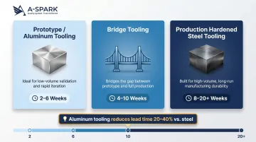
Doubling cavity count typically increases build time by 30-40%, not 100%. Pre-hardened P20 steel molds can often be ready in 15-20 days because they skip post-machining heat treatment. Aluminum tooling reduces lead times by 20-40% compared to steel.
Step 1: Mold Design and Engineering
Mold design translates part geometry into a tool design, including:
- Parting line placement — where the two mold halves separate
- Runner and gate layout — how plastic flows into the cavity
- Ejector pin positioning and cooling channel routing
- Side actions or lifters for any undercut features
This is where DFM analysis occurs — every decision becomes permanent once steel is cut. Parting line placement determines visible witness lines; gate location drives fill balance, knit line position, and cycle time.
With the tool design locked, material selection is the next variable that determines both mold cost and production longevity.
Step 2: Mold Material Selection
The choice between hardened tool steel, pre-hardened steel, and aluminum determines both upfront cost and mold lifespan:
| Material | Hardness | Shot Life | Best For |
|---|---|---|---|
| Aluminum (7075) | ~160 HB | 10,000+ shots (up to 2.3M demonstrated) | Prototyping, low-volume production |
| P20 (pre-hardened) | ~33 HRC (310 HB) | 50,000-100,000 shots | Medium-volume, faster delivery |
| H13 (hardened) | 45-52 HRC | 500,000-1,000,000+ shots | High-volume production |
| S136 (stainless, hardened) | 45-52 HRC | 500,000-1,000,000+ shots | Corrosive resins, medical, optical |
Hardened steel molds are more expensive to machine but offer superior wear resistance. Aluminum molds are faster and cheaper to produce but suited for low-to-medium volume runs. Beryllium-copper inserts in strategic locations (typically the core) reduce cooling cycles by 20-50% due to copper's roughly 10x higher thermal conductivity versus steel.
Critical context: Raw steel represents only 5-10% of total mold cost. Machining accounts for roughly 33%, and polishing can consume up to 30% of total cost.
Step 3: CNC Machining and EDM
CNC milling removes metal from a solid block to create the cavity and core — the negative of the final part geometry. EDM (Electrical Discharge Machining) follows to resolve fine details, sharp internal corners, and complex features that rotating cutters cannot reach.
EDM applications in mold fabrication:
- Sharp internal corners on contoured surfaces
- V-shaped features (e.g., energy directors for ultrasonic welding, min 0.020 in. × 0.020 in.)
- Crush ribs and deep ribs/cavities
- Fine details including gear teeth and piercing features
EDM uses a graphite electrode with dielectric fluid to erode material via electrical discharge — no cutting force, no tool deflection. For features smaller than 0.04 in. (1.0 mm), maintain a 1:1 width-to-depth ratio. One practical note: EDM stock removal rates on aluminum run 4-5 times faster than on steel, which contributes directly to aluminum tooling's shorter lead times.
Step 4: Surface Treatment and Finishing
After machining, mold surfaces are polished, textured, or coated depending on the required cosmetic finish of the molded part. Polishing levels range from standard (non-cosmetic) to mirror-finish (for optical or high-appearance parts).
SPI surface finish standards include 12 grades in 4 categories:
| Category | Grades | Method | Application |
|---|---|---|---|
| A - Glossy | A-1, A-2, A-3 | Diamond polish (6000/3000/1200 grit) | Optical/transparent parts, mirrors, lenses |
| B - Semi-Glossy | B-1, B-2, B-3 | Grit paper (600/400/320 grit) | Medium-shine parts, clips |
| C - Matte | C-1, C-2, C-3 | Stone polish (600/400/320 grit) | Industrial parts |
| D - Textured | D-1, D-2, D-3 | Dry/glass bead blast | Rough/textured finish, hiding imperfections |
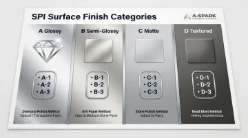
Finish grade also determines how much draft angle the part design requires. Insufficient draft on textured walls causes drag marks and ejection damage — a common source of T1 trial failures.
Texturing and draft requirements:
Current Mold-Tech guidance recommends 2 to 2.5 degrees of draft per 0.001 in. of texture depth for shrink-away sidewall applications. Shrink-on-to-steel areas require 3 times the draft (6-7.5 degrees per 0.001 in.). Light textures (PM-T1) require minimum 3 degrees; heavy textures (PM-T2) require minimum 5 degrees.
Step 5: Mold Trials and Validation
Before full production, the completed mold undergoes trial runs (T1, T2 shots) where sample parts are inspected for dimensional accuracy, surface quality, fill balance, sink, flash, and warpage. Parameters such as injection pressure, temperature, and cooling time are adjusted during this stage. Mold modifications may be required before sign-off.
A-SPARK's on-site engineers support the full validation phase — reviewing T1 shot data, coordinating mold modifications, and producing PPAP documentation before production release. IATF 16949-certified quality controls apply from first shot through approval.
Critical Design Principles That Shape the Mold
Wall Thickness Uniformity
Non-uniform wall thickness causes differential cooling, leading to sink marks, warpage, and voids. The mold must be designed around consistent wall sections, with cored-out geometry used to eliminate thick areas.
Industry guideline: Ribs should not exceed 50-60% of adjacent wall thickness to prevent sink marks while maintaining strength.
Recommended wall thickness by resin:
| Resin | Range (inches) | Range (mm) |
|---|---|---|
| ABS | 0.045 - 0.140 | 1.14 - 3.56 |
| Polypropylene (PP) | 0.025 - 0.150 | 0.64 - 3.81 |
| Polycarbonate (PC) | 0.040 - 0.150 | 1.02 - 3.81 |
| Nylon (PA) | 0.030 - 0.115 | 0.76 - 2.92 |
Draft Angles
Draft (typically 1-2 degrees on vertical walls, more for textured surfaces) is machined into the mold to allow the part to release from the cavity without sticking, warping, or damaging the mold surface.
- Minimum: 0.5 degrees on all vertical faces
- Standard: 1-2 degrees for most situations
- Shutoffs (metal-on-metal): Minimum 3 degrees
- Rule of thumb: 1 degree per 1 inch of cavity depth
- Light texture (PM-T1): Minimum 3 degrees
- Heavy texture (PM-T2): Minimum 5 degrees or more
Insufficient draft is one of the most common causes of mold damage and part defects.
Gate Design and Placement
The gate is the entry point for molten plastic into the cavity. Its location, type, and size all shape how the part fills — affecting knit line placement, cosmetic appearance, and cycle time. Poor gate placement is nearly impossible to correct after fabrication.
Common gate types include:
- Tab gate — easy to trim; suited for flat, flexible parts
- Hot tip gate — gapless entry; ideal for cosmetic surfaces
- Tunnel/submarine gate — auto-degates on ejection; good for hidden locations
Undercuts and Side Actions
Undercuts are part features that prevent straight ejection from the mold. Resolving undercuts requires adding mechanical components — side actions/cams, lifters, or pickouts — which increase fabrication complexity and cost. Designers should eliminate undercuts by default or flag them explicitly before tooling begins.
Parting Line and Ejector Pin Strategy
The parting line defines where the two mold halves separate and should be placed to minimize visible witness lines on the finished part. Position ejector pins on non-cosmetic surfaces and distribute them evenly to prevent distortion during ejection. Neither decision can be undone after machining — getting both right at the design stage protects tooling investment and part quality downstream.
Key Factors Affecting Mold Fabrication Cost and Lifespan
Cavity Count
Single-cavity molds are simpler and cheaper to fabricate but have lower throughput. Multi-cavity molds (2, 4, 8, 16+ cavities) increase fabrication cost and complexity but dramatically reduce cost-per-part at production volumes.
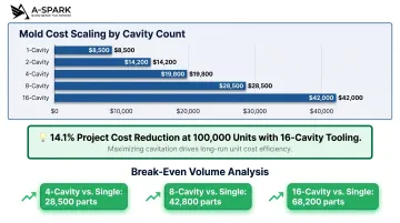
Cost scaling rule: Each additional cavity typically costs 15-30% less than the previous one.
Example (complex housing, 150mm):
- 1-cavity: $8,500
- 2-cavity: $14,200 (1.7×)
- 4-cavity: $19,800 (2.3×)
- 8-cavity: $28,500 (3.4×)
- 16-cavity: $42,000 (4.9×)
At 100,000 units, cost-per-part drops from $0.726 (single-cavity) to $0.623 (16-cavity)—a 14.1% project cost reduction.
Break-even volumes: 4-cavity vs. single = 28,500 parts; 8-cavity vs. single = 42,800 parts; 16-cavity vs. single = 68,200 parts.
Part Complexity and Feature Count
Undercuts, threads, deep ribs, thin walls, tight tolerances, and fine surface textures each add machining time, EDM passes, and engineering review cycles. Of all cost drivers, complexity carries the most weight — more so, even, than the steel grade selected.
Steel Grade and Mold Material
The cost-versus-lifespan tradeoff here is straightforward once you know the options:
- P20 pre-hardened steel — lower upfront cost, but wears faster in high-volume runs
- H13 hardened tool steel — higher fabrication cost; supports 500,000 to 1 million+ shots
- Aluminum tooling — best for prototypes or sub-100,000 unit runs where speed-to-first-part matters more than longevity
Tolerances and Shrinkage Compensation
Tighter dimensional tolerances require additional machining passes, inspection steps, and sometimes post-hardening rework. Medium tolerances cost 1.7× normal; fine tolerances cost 3.0× normal.
Shrinkage compensation (the mold is machined slightly oversized to account for plastic shrinkage on cooling) must be calculated per resin and validated during trial shots. Shrinkage rates vary between 0.001/in/in and 0.020/in/in; industry average is approximately 0.006/in/in. Errors here result in out-of-spec parts that require costly mold rework.
Typical tolerance range for precision injection mold fabrication:
| Resin | Commercial (to 1.000 in.) | Fine (to 1.000 in.) |
|---|---|---|
| ABS | ±0.005 | ±0.003 |
| Polycarbonate | ±0.004 | ±0.003 |
| Polypropylene | ±0.007 | ±0.004 |
Fabricator Capabilities and Certification
Mold quality ultimately depends on three things a fabricator either has or doesn't:
- Equipment: Multi-axis CNC centers, EDM, CMM inspection
- Engineering depth: DFM support, flow simulation, tolerance review
- Quality systems: ISO 9001 baseline; IATF 16949 required for automotive-grade tooling
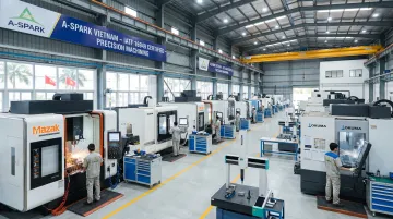
A-SPARK Manufacturing checks each of these boxes through its Vietnam-based facilities. The operation runs 15 sets of 3-, 4-, and 5-axis CNC milling machines, carries IATF 16949 certification, and handles tool design, fabrication, and maintenance under one roof — which matters when schedules slip and accountability needs to be clear.
Common Misconceptions About Injection Mold Fabrication
"The mold is a one-time cost with no ongoing impact"
A poorly fabricated mold creates recurring problems: inconsistent cycle times, higher scrap rates, frequent maintenance downtime, and dimensional drift over time. The mold is not a sunk cost but an asset whose quality determines production efficiency for its entire service life.
"Aluminum molds are always cheaper than steel molds"
Aluminum molds carry lower upfront fabrication costs (starting at approximately $1,500 vs. $50,000+ for steel), but the comparison doesn't end there. The real cost picture depends on volume, resin type, and tolerance requirements:
- Aluminum wears faster and requires more frequent maintenance at high volumes
- Aluminum is unsuitable for abrasive resins or tight-tolerance parts
- Aluminum cycle times run 30–50% faster than steel due to superior heat dissipation
- Steel tooling is recommended for 1 million+ units, where lower per-part cost justifies the upfront investment
- Above certain production thresholds, aluminum's total cost of ownership often exceeds properly specified steel
"Mold design changes are easy to make after fabrication"
Adding material to a mold — for example, to reduce a cavity dimension — is extremely difficult or impossible without scrapping and remaking mold components. Steel can be removed but not added. This makes pre-fabrication DFM review essential. Changes after T1 samples can add weeks to the schedule and multiply tooling costs — catching geometry issues before steel is cut is far cheaper than correcting them afterward.
Frequently Asked Questions
How much does it cost to make a plastic injection mold?
Mold cost varies widely based on complexity, cavity count, and steel grade. Simple single-cavity prototype tooling ranges from $3,000–$6,000. Production multi-cavity steel molds range from $25,000–$100,000+. Higher upfront tooling cost typically translates to lower cost-per-part at volume.
How is a plastic injection mold made?
A mold is made through five key stages: mold design and DFM analysis, material selection (steel grade), CNC machining and EDM to create the cavity, surface finishing (polishing or texturing), and mold trials/validation before production release. Each stage builds on the precision of the previous one.
What are the 4 steps of injection molding?
The four stages of the injection molding cycle (once the mold is fabricated) are: mold clamping (closing and securing the two mold halves), plastic injection into the cavity under pressure, cooling and solidification inside the mold cavity, and ejection of the finished part. Cycle times range from 2 seconds to 2 minutes.
What are the limitations of injection molding?
Three key limitations apply: high upfront tooling cost makes it unsuitable for very low volumes; part design must follow moldability rules (draft angles, uniform walls, no sharp undercuts without additional tooling); and mold fabrication lead times of 8–20+ weeks make it a poor fit for rapid design iteration.
What is the general tolerance for injection molded parts?
Tolerances depend on resin type, part geometry, and mold quality. Stable engineering resins (ABS, PC) achieve commercial tolerances of ±0.004–0.005 in. and fine tolerances of ±0.002–0.003 in. for dimensions up to 1.000 in. Semi-crystalline resins (PP, PE) require wider tolerances.
What is the difference between overmolding and insert molding?
Insert molding places a pre-made component (typically metal) into the mold before injection so plastic flows around it to form a single integrated part in one shot. Overmolding injects a second material over an already-molded substrate part, typically to add grip, color, or multi-material properties—requiring two molds or a two-shot mold.