Introduction
Automotive electronics engineers face a brutal reality: components like sensors, connectors, and control modules must survive extreme heat, continuous vibration, chemical exposure, and moisture infiltration — conditions that destroy unprotected electronics within months. Under-hood temperatures routinely exceed 125–150°C during operation, while engine-mounted connectors endure up to 12.1g RMS random vibration across 5–2000 Hz for eight hours per axis. Brake fluid, engine oil, coolant, and road salt attack unprotected PCB surfaces and connector housings daily. Standard electronic assemblies cannot withstand this environment.
Plastic overmolding is the primary solution to this problem — but it's routinely misapplied. Teams confuse it with potting or conformal coating, misselect materials, or use it where it adds cost without benefit.
When the process goes wrong, the failures are predictable: material incompatibility causes delamination, incorrect gate positioning creates weld lines at stress points, and thermal mismatch between substrate and overmold leads to cracking under temperature cycling.
This guide covers what plastic overmolding is, how the process works, where it's applied in automotive electronics, and what to avoid. The focus is on the variables that matter most: material pairing, mold design, thermal performance, and validation protocols — the difference between a reliable program and a warranty problem.
Key Takeaways
- Overmolding encapsulates electronic components in a protective plastic or elastomeric shell via multi-stage injection molding
- Automotive environments impose thermal extremes (-40°C to +150°C), 12.1g vibration, and chemical exposure that standard assembly cannot survive
- Mismatched substrate-to-overmold polymers are the leading cause of delamination failures — material compatibility determines bond integrity
- Process validation requires IATF 16949 documentation, PPAP submission, and Cpk ≥ 1.67 for automotive supply chains
- Not always the right choice — potting or conformal coating may be more appropriate for low volumes or complex internal geometries
What Is Plastic Overmolding?
Plastic overmolding is a manufacturing process where a secondary plastic or elastomeric material is injection-molded over a substrate — a rigid plastic part, metal component, or populated PCB. The result is a single integrated assembly, mechanically bonded and produced without secondary joining steps.
What distinguishes overmolding from closely related processes:
- Insert molding places a pre-fabricated part (often metal) in a mold and plastic is injected around it in one step
- Overmolding is a sequential multi-shot process where the substrate is itself a molded part
- Conformal coating applies a thin chemical film rather than a structural layer
- Potting fills an entire enclosure with liquid resin, encapsulating components without geometric control
Unlike these alternatives, overmolding delivers environmental sealing, structural reinforcement, and geometric precision in one consolidated part — no secondary assembly required.
Why Automotive Electronics Specifically Needs Overmolding
Operating Temperature Extremes
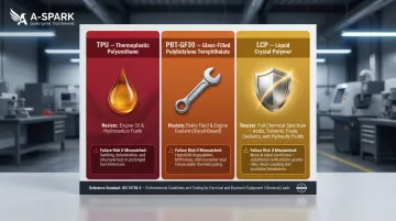
The Automotive Electronics Council defines temperature grades for integrated circuits under AEC-Q100. Grade 0 components must survive -40°C to +150°C ambient temperatures for powertrain and on-engine applications, while Grade 1 extends to +125°C for general under-hood use. This 190°C span forces the overmold material selection toward PA66-GF (Heat Deflection Temperature of 250°C at 1.8 MPa), LCP (230–340°C HDT), or PBT-GF30 (205°C HDT) — materials that maintain dimensional stability and seal integrity across thousands of thermal cycles.
Components cycle between cold starts and full thermal load throughout a vehicle's service life. Standard thermoplastics soften, warp, or degrade under sustained high-temperature exposure, creating leak paths at the substrate interface or dimensional changes that break seals.
Mechanical Stress Profile
USCAR-2 Section 5.4.6 defines vibration Class V2 for engine-mounted connectors: 12.1g RMS random vibration across 5-2000 Hz for 8 hours per axis. Road vibration, physical shock from potholes, and cable pull forces at connectors place continuous dynamic loads on solder joints and crimped terminals. Unprotected assemblies fail at these stress concentration points.
Overmolding addresses this by distributing mechanical loads across the encapsulated assembly rather than concentrating them at individual solder joints or crimps. The overmold absorbs vibration energy and couples the cable jacket to the connector housing, preventing the relative motion that causes fretting corrosion or contact degradation.
Chemical Exposure Barrier
ISO 16750-5:2023 defines exposure to over 30 chemical agents including engine oil, brake fluid, fuel, coolant, urea, and cleaning solvents at temperatures up to Tmax for durations up to 22 hours. Unprotected PCB surface finishes and connector housings degrade under these exposures — corrosion initiates at plating edges, flux residues attract moisture, and polymer housings swell or crack.
A correctly selected overmold material acts as a chemical barrier matched to the specific exposure profile. TPU resists oil and fuel; PBT-GF30 withstands brake fluid and coolant; LCP provides superior chemical inertness across the full fluid spectrum. Material selection errors lead to swelling, stress cracking, or plasticizer extraction that compromise the seal.
EMI Shielding and IP Rating Convergence
Automotive ECUs and sensor modules must meet both ingress protection ratings and electromagnetic compatibility requirements. IP67 demands dust-tight construction and immersion resistance up to 1 meter for 30 minutes; IP69K adds protection against close-range, high-pressure, high-temperature water jets. EMC requirements limit radiated emissions and ensure immunity to external interference.
Overmolding handles both simultaneously. Conductive fillers or integrated shield features can be incorporated into the overmold structure, providing the mechanical seal and EMI containment in a single operation. Conformal coating alone cannot achieve this — it offers no path to IP69K compliance or integrated shielding.
Regulatory and Quality Management Context
Automotive supply chains require IATF 16949 compliance and process validation through PPAP (Production Part Approval Process). Overmolding is classified as a special process where output quality cannot be fully verified by inspection alone — this triggers mandatory process validation under IATF 16949 clause 8.5.1.2. Initial process capability must demonstrate Cpk ≥ 1.67, with ongoing production maintaining Cpk ≥ 1.33.
PPAP Level 3 — the industry default for automotive molded parts — requires complete supporting data across several documentation categories:
- Process flow diagrams and PFMEA
- Control plans and dimensional results
- Material test reports and process capability studies
- Material traceability records
A-SPARK Manufacturing holds IATF 16949 certification and manages this full documentation package as part of standard production onboarding — which matters when OEM qualification timelines are tight and re-submissions are costly.
How Plastic Overmolding Works for Automotive Electronics
Overmolding follows a controlled sequence. A substrate — connector assembly, sensor housing, or PCBA — is loaded into a precision mold. Thermoplastic or elastomeric material is then injected to flow around and bond with it. The assembly cures, is demolded, and undergoes dimensional and functional validation.
Four inputs drive every overmolding job:
- Substrate (connector, sensor housing, or PCBA)
- Overmold material (PA66, PBT, TPU, TPE, or LCP for automotive applications)
- Mold tooling designed around substrate geometry
- Process parameters (injection temperature, pressure, mold temperature, cycle time)
Critical Role of Mold Design
Gate positioning determines how material flows around the substrate and where weld lines form.
A weld line positioned over a stress concentration point or near a connector pin is a common failure cause. Draft angles, parting line placement, and vent design all affect flash, surface quality, and dimensional conformance. Poorly designed tooling creates voids, short shots, or uneven wall thickness that compromise seal integrity.
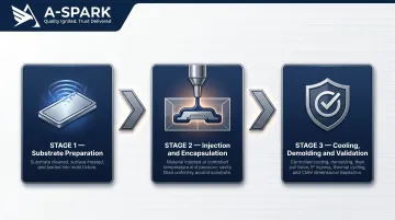
Step 1: Substrate Preparation and Loading
The electronic substrate is cleaned, inspected, and if required, surface-treated (plasma treatment or chemical primer) to improve adhesion. Surface contamination — oils, mold release residue, oxidation — prevents molecular bonding at the interface.
The substrate is precisely loaded into the mold cavity using fixture guides. Misalignment at this stage leads to uneven overmold thickness or exposed substrate surfaces that fail IP testing. Fixture design must account for substrate dimensional tolerances and prevent movement during injection.
Step 2: Injection and Encapsulation
The overmold material is injected into the closed mold at controlled temperature and pressure. Material flows through the gate, fills the cavity around the substrate, and bonds either chemically (through material affinity) or mechanically (through designed undercuts and interlocks).
Automotive applications require controlled injection speeds to prevent substrate movement and ensure complete cavity fill without voids. Excessive injection pressure can deform the substrate or damage internal components; insufficient pressure creates short shots or incomplete encapsulation. Cycle times for overmolding are typically 1-2 minutes — a significant throughput advantage at production volumes.
Step 3: Cooling, Demolding, and Validation
The assembly cools under controlled conditions to minimize residual stress and differential shrinkage between substrate and overmold. Rapid cooling creates internal stress that leads to warpage or cracking; slow cooling extends cycle time and reduces throughput.
After demolding, each part is inspected dimensionally, visually, and functionally. Standard automotive validation includes:
- Pull force testing on cables (cable retention specification per customer requirements)
- IP ingress testing (water immersion for IP67, high-pressure spray for IP69K)
- Thermal cycling to confirm bond integrity across the operating temperature range
- Dimensional verification via CMM or optical inspection
Where Plastic Overmolding Is Applied in Automotive Electronics
Automotive Connectors and Wiring Harness Terminations
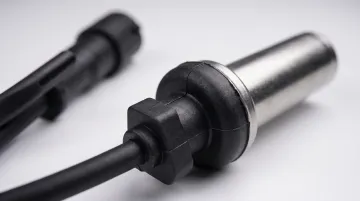
Overmolding is the standard protection method for connector-to-cable junctions in engine bay and chassis harnesses. The overmold provides strain relief and sealing against fluids, replacing separate rubber boots and secondary assembly operations.
Achieving this requires dual-material adhesion between the connector housing and cable jacket. Key design considerations include:
- Material pairing: TPU overmolds pair with PBT or PA66 housings for compatible surface energies and thermal expansion
- Strain relief geometry: Distributes cable pull forces over a larger area, preventing stress concentration at crimp or solder joints
- Seal continuity: Eliminates the assembly joints that separate boot-and-housing designs leave as ingress paths
Sensors (Wheel Speed, Temperature, Pressure, Position)
Sensor bodies are among the most widely overmolded components in a vehicle. These sensors are installed in harsh microenvironments — wheel wells, exhaust zones, transmission housings — where exposure to road spray, brake dust, salt, and temperature cycling is continuous.
Bosch's active wheel speed sensor uses a silicon IC hermetically sealed with overmolded plastic, enabling non-contact Hall-effect measurement down to 0.1 km/h. The overmold serves as the primary environmental barrier, maintaining seal integrity under vibration classes V1-V3 and ISO 16750 chemical exposure. The dual-material bond between sensor housing and cable jacket must survive years of thermal cycling and mechanical flexing without delamination.
Electronic Control Units and Power Electronics Modules
Enclosure-level overmolding is used on some ECU formats to integrate the housing, connector boot, and strain relief into one molded part, eliminating assembly joints that are potential ingress paths.
For EV applications, BMS connectors and high-voltage junction box components carry specific performance demands. These connectors must sustain voltages up to 800V with IP67 or higher sealing while supporting CAN, LIN, and Ethernet interfaces simultaneously.
TPE/TPU overmolds meet these demands by delivering abrasion resistance, automotive fluid resistance, and integrated secondary locking features suited to high-vibration environments.
ADAS and Camera/Radar Modules
Proximity to the vehicle exterior means ADAS sensor housings face UV exposure, precipitation, and temperature cycling. Overmolded enclosures with UV-stabilized materials and IP69K ratings are now standard for radar and camera module housings in Level 2+ automation systems.
These modules require dimensional stability to maintain optical alignment and calibration over the vehicle lifetime. LCP overmolds offer ultra-low moisture absorption, minimal thermal expansion, and inherent flame retardance (UL 94 V-0 without additives), making them a reliable choice for safety-rated systems where housing deformation or material degradation directly affects sensor performance.
Key Factors That Affect Overmolding Quality in Automotive
Material Compatibility
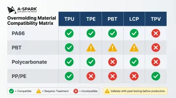
The overmold material must bond to the substrate — mismatched polymer families or incompatible surface energies are a leading cause of delamination failures. PP and PE have low surface energy and standard TPE/TPU grades do not bond to them; TPV (thermoplastic vulcanizates) is required for successful PP overmolding.
Automotive-grade combinations — TPU over PA66, PBT over PBT, LCP for high-frequency connectors — must be validated through peel testing before production.
Processing Conditions
Melt temperature, injection pressure, mold temperature, and cooling rate must be tightly controlled. Automotive overmolding processes are documented with a validated process window — deviations caused by barrel wear, material lot variation, or temperature drift can cause voids, short shots, or substrate damage.
Higher mold temperatures allow recrystallization at the insert surface, improving bond strength for PBT-GF30/TPU combinations.
Tooling Design and Maintenance
Mold wear affects parting line flash, dimensional repeatability, and gate vestige size. Automotive production molds require scheduled maintenance intervals and documented inspection records to sustain quality across high-volume runs — a requirement directly embedded in IATF 16949 process control documentation.
Gate location, venting, and draft angles must be optimized during initial tool design to prevent weld lines at critical locations.
Thermal Performance
In high-temperature zones — engine bay, exhaust proximity — the glass transition temperature (Tg) and heat deflection temperature (HDT) must exceed peak operating temperatures with sufficient margin. PA66-GF30 achieves HDT of 250°C at 1.8 MPa, PBT-GF30 reaches 205°C, and LCP grades span 230–340°C. Material selection maps directly to AEC-Q100 grade requirements.
Scale and Lot-to-Lot Consistency
Automotive production volumes can reach millions of parts annually. The overmolding process must maintain dimensional and adhesion consistency across lots — a requirement that depends on material supplier consistency, statistical process control (SPC) during production, and incoming material inspection protocols.
IATF 16949 requires Cpk ≥ 1.67 for initial process validation, with continuous SPC monitoring to detect process drift before non-conforming parts are produced.
Common Issues, Misconceptions, and Limitations
The Material Compatibility Misconception
The most common misconception: teams assume that any thermoplastic overmold will adhere to any substrate if injection parameters are correct. In reality, adhesion in overmolding is primarily a material chemistry interaction — polymer families with low surface energy (PP, PE) resist adhesion without surface treatment or adhesive layers.
Many automotive assemblies fail at the bond interface because this compatibility check was skipped during design. Substrate-specific requirements include:
- PA66: Requires moisture management before overmolding to prevent steam blisters and void formation
- Polycarbonate: Must stay just below softening temperature to prevent distortion while still achieving molecular interdiffusion
- PP/PE: Need surface treatment or adhesive layers — their low surface energy resists adhesion by default
Bond strength depends on surface roughness, wetting degree, and interdiffusion between insert and overmold materials.
Where Overmolding Is Misapplied
Overmolding is not always the right choice. For sealed enclosures with complex internal geometry — or low-volume components where tooling amortization is prohibitive — potting compounds (two-part epoxy or polyurethane) or conformal coatings are more cost-effective.
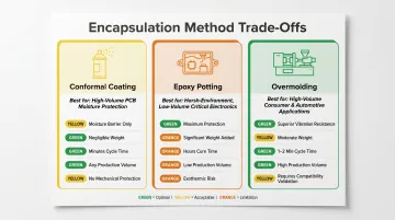
| Attribute | Conformal Coating | Epoxy Potting | Overmolding |
|---|---|---|---|
| Protection Level | Moisture barrier only | Maximum (up to 250°C) | Superior vibration/impact resistance |
| Weight Impact | Negligible | Significant increase | Moderate |
| Cycle Time | Minutes | Hours (batch cure) | 1-2 minutes |
| Volume Suitability | Any | Limited by batch constraints | High volume (inline processability) |
| Key Risk | No mechanical protection | Exothermic cure damages components | Requires compatibility validation |
Overmolding is preferred for high volumes, defined geometries, and where structural integration is required — using it by default in low-volume or complex-cavity applications adds cost without proportional benefit.
Overmolding vs. Insert Molding Confusion
Insert molding places a pre-fabricated part (metal pin, threaded insert) into a mold before the first shot; overmolding adds a second material layer over an already-molded substrate. In practice, automotive connector assemblies often combine both — metal contacts are insert-molded into a plastic housing, and then that housing assembly is overmolded with a TPU strain relief.
Teams that conflate the two processes make tooling and process planning errors that delay production. The distinction matters most at the DFM stage: insert molding requires the insert to survive injection pressure in a single shot, while overmolding requires the substrate to survive a second thermal cycle — two different validation checkpoints with different failure modes.
Conclusion
Plastic overmolding is a validated, structurally integrated protection method that addresses the thermal, mechanical, chemical, and sealing requirements automotive operating environments impose on electronic assemblies — requirements no single alternative process fully meets. It delivers IP-rated sealing, strain relief, chemical resistance, and EMI containment in a single molded part, eliminating secondary assembly operations and potential failure points.
That value is realized only when material selection, mold design, process parameters, and post-mold validation are engineered together around the application's specific demands. Treating overmolding as a default choice without compatibility validation introduces predictable failure modes: material pairing errors cause delamination, incorrect gate positioning creates weld lines at stress points, and inadequate thermal performance leads to warpage or seal failure under temperature cycling.
For automotive OEMs and Tier 1/2 suppliers sourcing overmolded electronic components from Asia, the manufacturer's process discipline is as important as its certifications. A-SPARK Manufacturing's IATF 16949-certified facilities in Vietnam offer dedicated engineering support, documented process control, and full PPAP documentation capability — reducing qualification risk across the prototype-to-production cycle. Material traceability and in-house quality verification mean fewer qualification surprises and a more predictable path to series production.
Frequently Asked Questions
What does "overmolded" mean?
"Overmolded" describes a part that has had a second material injection-molded directly over it to create a single integrated assembly. This combines the structural properties of the substrate (rigidity, electrical function) with the protective properties of the overmold layer (sealing, strain relief, chemical resistance).
What is an example of overmolding in automotive electronics?
A wheel speed sensor where the sensor body and cable junction are encapsulated in a TPU overmold that provides IP67 sealing, strain relief, and chemical resistance in a single molded part. The overmold replaces separate boots and mechanically couples the cable to the housing, preventing relative motion under vibration.
Is overmolding expensive?
Overmolding has higher upfront tooling costs than conformal coating or potting, but at automotive production volumes the per-part cost is low. Total cost of ownership (warranty reduction, rework elimination, and assembly labor savings) typically favors overmolding for medium-to-high volume applications above several thousand units annually.
What materials are typically used for overmolding automotive electronics?
TPU, TPE, PBT, PA66-GF, and LCP are the most common automotive overmold materials. Material selection depends on operating temperature range, chemical exposure, and substrate compatibility. Temperature thresholds span from ~80°C (TPU) through 205°C (PBT-GF30) and 250°C (PA66-GF) up to 340°C (LCP).
How does overmolding differ from potting in automotive electronics?
Potting fills an entire enclosure with liquid resin that cures in place (no mold required), while overmolding uses injection molding to form a geometrically precise, structurally bonded layer. Overmolding is preferred for defined geometries and high volumes; potting for complex internal layouts, low volumes, or maximum temperature resistance (up to 250°C).
Does automotive overmolding need to meet IATF 16949 requirements?
Yes. Automotive supply chains require IATF 16949 process documentation, material traceability, and PPAP submission for overmolded components. Overmolding is classified as a special process requiring validated parameters and Cpk ≥ 1.67 initial capability — your manufacturing partner must hold IATF 16949 certification to meet OEM qualification.