This guide covers the full aluminum die casting process from definition through alloy selection, applications, design considerations, and how to identify a qualified manufacturing partner for your production needs.
Highlights
- Aluminum die casting injects molten aluminum under high pressure (1,500–25,400 psi) into reusable steel dies to produce precise, complex parts at scale
- Cold chamber machines are required for aluminum due to its high melting point (660°C / 1,220°F)
- A380, A360, B390, and A413/ADC12 are the most common alloys, each suited to different mechanical and environmental needs
- Primary industries served: automotive, EV, electronics, lighting, and oil & gas
- Best economics start at 1,000+ units — high tooling costs favor medium-to-high production volumes
What Is Aluminum Die Casting?
Aluminum die casting is a high-pressure metal forming process that injects molten aluminum into a hardened steel mold (called a die) to create precise, complex parts. The process uses injection pressures typically ranging from 1,500 to 25,400 psi (10 to 175 MPa), forcing the liquid metal to fill every detail of the die cavity. This differs from gravity-fed methods like sand casting, where molten metal is poured into a mold without applied pressure.
The high-pressure injection enables aluminum die casting to achieve tight dimensional tolerances (±0.010 in for the first inch per NADCA standards), excellent surface finish, and the ability to cast thin walls and intricate geometries that other processes cannot replicate efficiently. The steel dies are reusable for thousands or even hundreds of thousands of cycles, making the process highly cost-effective at volume.
How Aluminum Die Casting Differs from Other Forming Methods
| Process | How It Works | Key Limitation vs. Die Casting |
|---|---|---|
| Extrusion | Pushes aluminum through a shaped opening to create uniform cross-sections | Cannot produce 3D parts with varying wall thickness or internal features |
| CNC Machining | Removes material from solid stock (subtractive) | Higher per-part cost and more material waste at volume |
| Sand Casting | Uses single-use bonded sand molds filled by gravity | Lower dimensional accuracy, rougher surface finish, slower cycle times |
Why Aluminum Is the Preferred Die Casting Metal
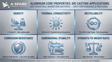
Aluminum offers the best balance of properties for most die casting applications:
- At 2.76 g/cm³, aluminum is roughly one-third the density of steel — enabling automotive brackets and EV housings to meet weight targets without sacrificing load capacity
- Thermal conductivity of 96 W/m·K makes it the go-to choice for heat sinks, LED housings, and electronic enclosures that need efficient heat dissipation
- A naturally forming oxide layer provides corrosion resistance superior to zinc in marine, outdoor, and industrial environments
- 75% of all aluminum ever produced is still in use today — scrap from die casting operations feeds directly back into production, cutting material costs
- Low thermal expansion keeps part dimensions stable across temperature swings, which matters for structural and precision-fit assemblies
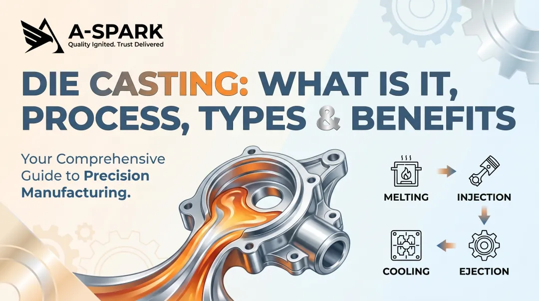
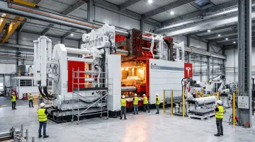
How the Aluminum Die Casting Process Works Step by Step
Cold Chamber vs. Hot Chamber Die Casting
Aluminum always requires cold chamber die casting rather than hot chamber machines. This distinction is critical due to aluminum's melting point of approximately 660°C (1,220°F), which would rapidly erode and destroy the submerged plunger and gooseneck components used in hot chamber systems.
Hot chamber machines keep the injection mechanism immersed in molten metal and are limited to metals with melting points below approximately 450°C (842°F)—primarily zinc, tin, and lead-based alloys. The gooseneck fills automatically from the furnace reservoir, enabling cycle times as fast as 15 shots per minute.
Cold chamber machines keep the furnace separate. For each cycle, molten aluminum is ladled from the furnace into a horizontal shot chamber, then a hydraulic piston rapidly injects the metal into the die. This protects injection components from prolonged exposure to molten aluminum but results in slower cycle times—typically 75–88 shots per hour for aluminum die casting operations.
With that machine context in place, here's how each production cycle unfolds from tooling preparation through finished part.
Step-by-Step Process Overview
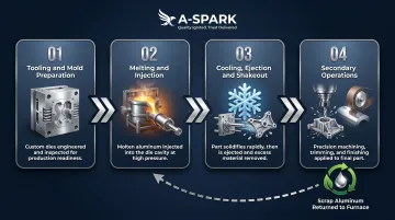
Step 1 — Tooling and Mold Preparation
The hardened steel die consists of two halves: the cover die (typically containing the cosmetic surface) and the ejector die (containing ejector pins and mechanisms). Before each cycle, the die is sprayed with a water-based lubricant to control temperature and facilitate part release. Key mold design elements include:
- Parting line: Where the two die halves separate; determines seam marks and affects tolerances
- Injection gates: Entry points where molten metal enters the cavity
- Ejector pins: Push the solidified part out after the die opens
- Draft angles: Minimum 0.6° to 2° taper to allow part ejection without damage
- Venting: Allows trapped air to escape during injection, preventing gas porosity
Step 2 — Melting and Injection
Aluminum alloy ingots are melted in a separate furnace. A measured volume (the "shot") is ladled into the shot chamber and immediately injected into the closed die cavity under high pressure.
Pressure is maintained throughout solidification to ensure the metal completely fills thin sections and complex geometries. This sustained pressure also compensates for shrinkage as the aluminum cools.
Step 3 — Cooling, Ejection, and Shakeout
Aluminum solidifies rapidly due to heat transfer into the steel die. Cycle times range from seconds for small parts to several minutes for large, thick-walled castings. Once solidified, the die opens, ejector pins push the part and attached runner system out, and the casting is separated from the gates, runners, and flash. All scrap aluminum is recycled back into the furnace.
Step 4 — Secondary Operations
Many aluminum die cast parts skip extensive post-processing — as-cast tolerances typically reach ±0.1–0.2 mm with smooth surface finishes. Where tighter specs are required, common secondary operations include:
- Trimming: Removing gates, runners, and flash
- CNC machining: Adding tight-tolerance features like threaded holes, bearing surfaces, or critical dimensions
- Shot peening: Improving fatigue resistance by inducing compressive surface stresses
- Surface finishing: Anodizing, powder coating, or chemical film treatments for corrosion protection and aesthetics
Parts then move through final dimensional inspection and functional checks before shipment.
Key Advantages and Limitations of Aluminum Die Casting
Core Advantages
Aluminum die casting delivers several distinct manufacturing benefits that make it the process of choice for high-volume production:
- Tight dimensional tolerances: NADCA standard tolerances of ±0.010 in (±0.25 mm) for the first inch, with precision tiers available at higher cost
- Excellent surface finish: As-cast surfaces often require no further finishing, reducing secondary operations
- Thin walls and complex geometries: Minimum wall thickness of 0.89 mm (0.035 in) with the ability to cast intricate features, ribs, bosses, and undercuts
- Fast cycle times: High-speed production for large volumes, with cycle times measured in seconds to minutes depending on part size
- Low per-part cost at scale: Fixed tooling costs are amortized across thousands of units, driving unit costs down significantly
These advantages are most pronounced when production volumes exceed 1,000–5,000 units, the threshold where tooling investment becomes economically justified.
Main Limitations
Die casting's strengths come with real trade-offs. Key limitations to evaluate before committing to the process:
- High upfront tooling costs: Steel die fabrication runs $15,000–$150,000 depending on part size and complexity; gigacasting-scale structural dies can reach several million dollars. Under 1,000 units, CNC machining or sand casting is typically more cost-effective.
- Porosity constraints: Trapped air and insufficient feeding during solidification create gas and shrinkage porosity. This prevents conventional heat treatment (gas expansion causes surface blistering) and limits weldability. Vacuum-assisted HPDC reduces porosity significantly and enables structural applications, but adds cost.
- Alloy limitations: The process requires high-fluidity alloys optimized for die casting. Common wrought alloys like 6061 — widely used in extrusion and machining — are unsuitable due to hot cracking tendencies, die sticking, and poor castability.
Understanding these limitations helps clarify where die casting fits relative to alternative processes.
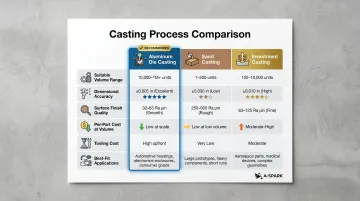
Comparison with Other Casting Processes
Sand casting uses bonded sand molds destroyed after each pour, making it suitable for low volumes (10-500 units) and large parts (engine blocks, pump housings). It delivers lower dimensional accuracy (±0.030 in typical) and rougher surface finish, requiring extensive machining.
Investment casting creates extremely intricate parts using wax patterns and ceramic shells, ideal for small quantities (50-5,000 units) with complex geometries like turbine blades and medical implants. It offers excellent surface finish but at significantly higher per-part cost than die casting.
Aluminum die casting wins on surface finish, dimensional consistency, and cost efficiency for volumes above 5,000 units, making it the dominant process for automotive, electronics, and consumer products.
Common Aluminum Die Casting Alloys Explained
Alloy selection directly impacts castability, mechanical performance, corrosion resistance, and cost. The North American Die Casting Association (NADCA) provides verified mechanical properties and castability ratings for the most common alloys.
A380 — The Industry Workhorse
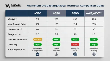
Properties: UTS 47,000 psi (324 MPa) | Yield 23,000 psi (159 MPa) | Elongation 3.5% | Hardness 80 BHN
A380 is by far the most widely cast aluminum alloy, offering the best overall balance of castability, mechanical properties, and moderate corrosion resistance. It delivers good die-filling characteristics, low hot-cracking tendency, and acceptable machinability. For most applications, it's the logical starting point.
Typical applications: Electronic and communications equipment housings, automotive components (engine brackets, transmission cases), hand and power tools, and general-purpose industrial parts.
A360 — Superior Corrosion and High-Temperature Performance
Properties: UTS 46,000 psi (317 MPa) | Yield 24,000 psi (165 MPa) | Elongation 3.5% | Hardness 75 BHN
A360 features higher silicon content than A380, providing superior corrosion resistance and better strength retention at elevated temperatures. It rates best-in-class (rating of 1) for hot cracking resistance and excellent (rating of 2) for pressure tightness.
Typical applications: Marine components, hydraulic housings, pressure vessels, and applications requiring performance above 200°C.
Tradeoff: Slightly more difficult to cast than A380 (die-filling rating of 3 vs. 2), requiring careful gating and venting design.
B390 — Maximum Wear Resistance
Properties: UTS 46,000 psi (317 MPa) | Yield 36,000 psi (248 MPa) | Elongation <1.0% | Hardness 120 BHN
B390 is a hypereutectic aluminum-silicon alloy (16–18% Si) built around its high silicon content to maximize hardness and wear resistance. Its hardness of 120 BHN is 50% higher than A380, making it ideal for sliding wear applications.
Typical applications: Automotive engine blocks, valve bodies, sleeveless piston housings, and heavy-duty powertrain components.
Tradeoff: Lowest ductility of common alloys (<1% elongation), poor machinability (rating of 5), and the worst castability ratings (hot cracking rating of 4). Best suited when wear resistance is the primary design requirement and machinability or ductility can be sacrificed.
A413 / ADC12 — Best Pressure Tightness and Fluidity
Properties (A413): UTS 42,000 psi (290 MPa) | Yield 19,000 psi (131 MPa) | Elongation 3.5% | Hardness 80 BHN
A413 delivers the best pressure tightness (rating of 1) and die-filling capacity (rating of 1) of all common alloys, making it the top choice for hydraulic components, pressure vessels, and thin-walled parts requiring leak-tight performance.
ADC12 equivalence: ADC12 is standardized under JIS H 5302:2006 (Japan) and is the ANSI/AA equivalent of A383.0. It features nearly identical composition and properties to A413, serving as the Asian market workhorse with UTS 310 MPa, yield 150 MPa, and thermal conductivity of 96 W/m·K.
Typical applications: Hydraulic cylinders, intricate thin-walled electrical and telecom components, LED lighting housings, and parts requiring maximum fluidity for complex mold filling.
Tradeoff: Harder to machine than A380 (rating of 4 vs. 3), increasing secondary operation costs.
Why 6061 Aluminum Is NOT Suitable for Die Casting
Understanding which alloys work for die casting also means knowing which common alloys don't. 6061 is a widely used aluminum alloy — but it is a wrought alloy designed for extrusion and forging, not die casting. When used in die casting, 6061 sticks in the mold cavity, requires oversized gates (>3 mm vs. standard sizes), and demands higher draft angles. It does not deliver the same quality or mechanical performance as purpose-designed casting alloys like A380 or ADC12.
For die casting applications, always specify casting alloys (A380, A360, B390, A413/ADC12) rather than wrought alloys.
Industries and Key Applications of Aluminum Die Casting
Automotive and EV — The Dominant Market
The automotive sector accounts for over 63% of global aluminum die casting revenue in 2024. Traditional applications include transmission housings, engine brackets, cylinder head covers, suspension components, and structural body panels. The shift to electric vehicles has accelerated aluminum adoption due to lightweighting requirements—every kilogram removed from vehicle weight extends driving range and improves efficiency.
Gigacasting is reshaping how vehicles are built. Tesla eliminated more than 350 stamped steel parts by replacing them with single-piece aluminum structural castings for the Model 3, Model Y, and Cybertruck underbodies. Ford, Honda, Rivian, Volvo, and Chinese OEMs including BYD, Geely, NIO, and XPeng are now deploying 6,000–9,000-ton gigacasting machines for front/rear underbody modules and battery enclosures.
The tradeoff is real: fewer parts and simpler assembly come at the cost of higher tooling capital and more complex collision repair. For manufacturers, the part-count reduction typically wins.
A-SPARK Manufacturing serves this sector through its IATF 16949-certified facility in Bac Ninh, Vietnam, producing precision aluminum die cast components—transmission housings, EV battery enclosure parts, and thermal management assemblies—for automotive and EV customers across Asia and North America.
Electronics, Lighting, and Industrial Equipment
Aluminum die casting is essential for applications requiring thermal management, electromagnetic shielding, and dimensional accuracy:
- Heat sinks and thermal management: Aluminum's 96 W/m·K thermal conductivity makes it ideal for cooling high-power electronics and LED systems
- LED lighting housings: A413/ADC12 alloys enable thin-walled, pressure-tight designs for indoor, outdoor, and industrial lighting
- Motor enclosures and electronic shielding: Die cast aluminum provides EMI/RFI shielding while dissipating heat from motors and power electronics
- Pump housings and automation components: Pressure-tight castings in A360 and A413 alloys deliver reliable performance in hydraulic and pneumatic systems
Aerospace, Medical, Oil & Gas, and Renewable Energy
These sectors use aluminum die casting for applications demanding high strength-to-weight ratios and corrosion resistance:
- Aerospace: Structural brackets, instrument housings, and non-flight-critical components where every gram of weight saved matters
- Medical devices: Equipment housings and mounting brackets requiring biocompatible surface treatments
- Oil & gas: Valve bodies, pump components, and corrosion-resistant hardware (often using A360 alloy)
- Renewable energy: Solar panel mounting hardware, wind turbine components, and energy storage system enclosures
Parts for these industries must meet tight quality requirements, including ISO 9001:2015 and industry-specific certifications. A-SPARK's quality systems cover PPAP documentation, material certifications, and full traceability from raw material to finished component.
Design Considerations for Aluminum Die Cast Parts
Wall Thickness and Geometric Features
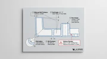
Minimum wall thickness: Aluminum die castings can achieve 0.89 mm (0.035 in) minimum section thickness, with thinner walls (0.030 in / 0.762 mm) achievable for small, optimized castings. However, uniform wall thickness throughout the part is more critical than chasing absolute minimums—inconsistent thickness causes shrinkage defects, porosity, and warping.
Design guidelines for wall thickness:
- Maintain uniform thickness wherever possible
- Transition gradually between thick and thin sections using tapers or blends
- Avoid isolated thick sections that create shrinkage sinks
- Use ribs rather than thick walls for structural strength
Draft angles: Minimum draft of 0.6° to 2° (depending on feature depth) is required to eject parts without damage. Inside walls generally require more draft (2° recommended) than outside walls (1° recommended) per NADCA guidance. More complex features need greater draft.
Ribs and bosses:
- Ribs: Thin vertical features that add structural strength without increasing overall wall thickness; should be 50-60% of nominal wall thickness
- Bosses: Cylindrical projections for mounting holes or fasteners; require adequate draft and fillet radii to prevent cracking
Fillets: Always use generous fillet radii at inside corners—sharp corners create stress concentrations that lead to cracking during solidification and service life. Minimum radius of 1 mm is recommended.
Parting Line, Injection Point Placement, and Undercuts
Parting line design: The parting line is where the two die halves meet and separate. Its placement must be decided early in the design phase because it determines where visible seam marks appear and affects dimensional tolerances.
NADCA parting line tolerances range from +0.0055 in (+0.14 mm) for small parts (up to 10 sq in projected area) to +0.012 in (+0.30 mm) for larger parts (51-100 sq in). Parting line tolerance is always a plus-only value — a closed die has zero separation, and injection pressure forces the halves apart slightly.
Injection point (gate) location: Gate placement affects mold filling, porosity distribution, and surface finish. Gates should be positioned to minimize flow distance, avoid direct impact on cores or thin walls, and ensure progressive filling without air entrapment. The final gate location is typically determined by the die casting engineer during mold design.
Undercuts: Features that prevent straight ejection from the die (threads, side holes, overhangs) require movable core slides or hydraulic mechanisms, adding 15–30% to tooling cost and cycle time. Best practice: Redesign to eliminate undercuts wherever possible. If unavoidable, evaluate whether post-cast CNC machining is more cost-effective than complex automated die slides.
Surface Finishing Options
Common post-processing options and their primary use cases:
- Anodizing — Grows a protective oxide layer; enables decorative coloring (clear, black, bronze, gold). Standard for consumer electronics, lighting, and outdoor equipment. Note: A380 and ADC12 anodize cleanly; high-silicon alloys like B390 produce uneven, grayish results.
- Powder coating — Electrostatically applied dry powder cured at high temperature; available in virtually any color. Preferred for automotive parts and industrial equipment needing impact resistance.
- Shot peening — Steel or ceramic bead blasting that induces compressive residual stress, improving fatigue resistance by 20–50%. Used for high-stress automotive and aerospace components.
- Chemical film / chromate conversion — Thin coating providing corrosion protection and paint adhesion. Common in military and aerospace; hexavalent chromate use is now restricted under environmental regulations, with trivalent alternatives widely available.
What to Look for in an Aluminum Die Casting Partner
Technical Capability and Quality Infrastructure
A qualified die casting partner should demonstrate:
- In-house tooling workshop that shortens lead times (typically 4–6 weeks) and enables rapid design iterations without depending on external tool shops
- Integrated CNC machining centers for tight-tolerance secondary features—threaded holes, bearing surfaces, precision datums—added immediately after casting
- On-site surface treatment (anodizing, powder coating, shot peening) to eliminate the logistics overhead and quality risk of outsourced finishing
- ISO 9001:2015 certification as the baseline for quality management; for automotive work, IATF 16949 is mandatory, validating PPAP, FMEA, control plans, and traceability
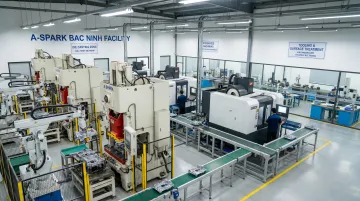
A-SPARK Manufacturing operates a fully equipped in-house aluminum and zinc die casting facility in Bac Ninh, Vietnam, with 27 presses ranging from 50 to 800 tons, an integrated tooling workshop, CNC machining centers, and surface treatment capabilities. The facility holds both ISO 9001:2015 and IATF 16949 certifications, ensuring automotive-grade quality systems.
Engineering Support and DFM Capability
The best die casting partners provide design-for-manufacturability (DFM) analysis during the quoting phase—before tooling is cut. DFM review identifies issues such as:
- Wall thickness inconsistencies that cause shrinkage
- Inadequate draft angles leading to ejection problems
- Gate placement that creates porosity or weld lines
- Alloy selection mismatches for the application's mechanical or corrosion requirements
Early DFM feedback reduces costly design changes after tooling investment and can meaningfully compress time-to-market compared to suppliers who build parts to print without engineering review.
Backed by LEGE Corp's 40+ years of die casting expertise in Taiwan and 20+ years of Vietnam operations, A-SPARK brings this engineering-first approach to every project—from T1 samples through mass production, secondary operations, and logistics coordination. For complex aluminum die casting projects, that combination of technical depth and integrated infrastructure is what keeps quality consistent and timelines on track.
Frequently Asked Questions
What is die-cast aluminum and how does it differ from other aluminum alloys?
Die-cast aluminum refers to parts produced through high-pressure die casting using specific casting alloys like A380, A360, B390, and ADC12—all formulated for mold-filling and castability. Wrought alloys like 6061 or 7075, by contrast, are engineered for extrusion and machining, gaining their strength through heat treatment rather than casting characteristics.
What aluminum alloys are best for die casting?
A380 is the most widely used alloy, balancing castability with solid mechanical performance. A360 suits corrosion-critical and high-temperature environments; B390 is the go-to for wear-resistant powertrain components. A413/ADC12 offers the best pressure tightness and fluidity for thin-walled electrical and hydraulic parts.
What is aluminum die casting used for?
Common applications span industries where complex geometry, tight tolerances, and volume production intersect:
- Automotive & EV: transmission housings, engine brackets, battery enclosures
- Electronics: heat sinks, EMI shielding housings
- Lighting: LED fixture housings and heat dissipation components
- Industrial: pump housings, motor enclosures, valve bodies
- Energy: oil & gas fittings, renewable energy mounting hardware
What is the minimum wall thickness for die-cast aluminum parts?
The minimum section thickness is approximately 0.89 mm (0.035 in), with 0.030 in achievable for small, optimized castings. Uniform wall thickness matters more than hitting the absolute minimum, since inconsistent sections cause shrinkage defects and porosity.
What car parts are made from cast aluminum?
Common automotive die-cast aluminum parts include transmission housings, engine brackets, cylinder head covers, EV battery enclosures, thermal management housings, and ECU enclosures. Some EV platforms now replace 350+ individual steel stampings with a single large aluminum casting — a direct result of lightweighting targets pushing the industry toward gigacasting.
How much does it cost to die-cast aluminum parts?
Steel dies typically cost $15,000–$150,000 depending on part size and complexity, but per-part costs drop sharply at volume. The process becomes cost-effective at production runs of 1,000–5,000+ units, where tooling investment is fully amortized across output.