Introduction
Sand casting accounts for approximately 43.5–45.6% of global metal casting output, making it the single most widely used casting process worldwide. It remains dominant because it delivers genuine versatility across automotive, aerospace, industrial machinery, and infrastructure applications — at a scale and cost no alternative process matches.
Yet engineers, procurement teams, and product designers frequently evaluate casting methods without a clear picture of how sand casting actually works. That gap leads to mismatched process selection, cost overruns when tolerances prove unachievable, or missed opportunities when complex geometries default to more expensive alternatives.
This guide breaks down the sand casting process in practical terms: how it works, where it excels, and when to choose it over die casting or investment casting.
Key Takeaways
- Sand casting uses compacted, bonded sand as a single-use mold to shape molten metal into complex parts
- Works with virtually all metals—steel, iron, aluminum, bronze—and scales from 20 grams to hundreds of tonnes
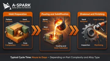
- Process sequence: pattern creation → mold assembly → metal pouring → solidification → shakeout → finishing
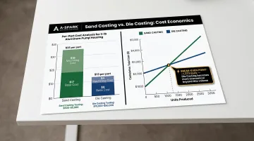
- Low tooling cost ($500–$7,500 vs. $7,500–$75,000 for die casting) makes it ideal for low-to-mid volumes
- Wider tolerances (CT7–CT10 per ISO 8062) and rougher surface finish mean post-machining is often required
What Is Sand Casting?
Sand casting is a metal casting process where molten metal is poured into a cavity formed in a mixture of sand and binding agents—clay, resin, or chemical binders. Once the metal solidifies, the part is extracted by breaking away the mold. The defining characteristic: the mold is expendable, destroyed after each pour.
This single-use nature solves a fundamental manufacturing challenge: producing complex, custom metal shapes without the high cost of permanent metal tooling. For one-offs, prototypes, or geometrically complex parts with internal passageways, no process offers a comparable combination of flexibility and low setup cost.
It's worth distinguishing sand casting from processes it's often compared to:
- Die casting injects molten metal into reusable hardened steel dies under high pressure — tighter tolerances, but expensive tooling that limits viable volumes and materials
- Investment casting uses wax patterns and ceramic shells — excellent surface finish, but higher per-part cost that rarely suits large or heavy components
- Permanent mold casting uses reusable metal molds — faster cycle times, but restricted design complexity and narrower material selection
Sand casting remains relevant despite newer alternatives because of three characteristics that no competing process replicates together: material compatibility (works with nearly every metal and alloy), size range (from 20 grams to hundreds of tonnes), and low barrier to entry (pattern costs are minimal compared to die casting tooling).
Types of Sand and Metals Commonly Used
The sand type directly affects surface finish, dimensional repeatability, and defect rates. Three primary systems dominate:
Green Sand
- Composition: Typically 89% sand, 4% water, 7% clay (bentonite), plus carbonaceous additives
- Surface finish: 6.3–12.5 µm Ra
- Tolerance capability: CT7–CT10 per ISO 8062 (varies with part size)
- Reusability: High — sand is easily reclaimed and recycled
- When to use: General-purpose applications where cost matters more than precision; fastest cycle times
Resin-Bonded (Chemically Bonded) Sand
- Binder system: Organic or chemical resins that cure at room temperature
- Surface finish: 3.2 µm Ra and above (1.6 µm achievable in some cases)
- Tolerance capability: CT7–CT9 (tighter than green sand for equivalent part sizes)
- Tradeoffs: Higher cost per mold; less sand reclamation; slower demoulding
- When to use: Parts requiring better dimensional stability and finer surface detail
Sodium Silicate (CO₂) Sand
- Binder system: Sodium silicate bonded sand, set by injecting CO₂ gas
- Characteristics: Strong, accurate molds; positioned between green sand and resin in cost and accuracy
- When to use: Producing sand cores for internal cavities (cooling passages in engine blocks, valve body internals)
Material choice is equally consequential. Sand casting works with all major cast metals — a breadth no other casting process fully matches:
Metals Commonly Cast
- Aluminum alloys: Lightweight components, transmission cases, brake cylinders
- Gray iron: Engine blocks, pump housings, heavy industrial components
- Ductile iron: Applications requiring impact resistance and flexibility
- Carbon and alloy steel: High-strength structural parts, gearbox housings
- Bronze and brass: Corrosion-resistant components, marine hardware, valve bodies
Critical advantage: Sand casting is the standard process for high-melting-point metals like steel (1,370–1,530°C) and iron, where die casting is not technically feasible. The American Foundry Society reports that 95% of die cast parts use non-ferrous metals — steel's melting point destroys die casting molds, leaving sand casting as the default process for ferrous metals at all volume levels.
How Does Sand Casting Work?
Sand casting moves through three distinct stages — mold preparation, pouring, and finishing — and errors in any one stage carry through to the final part. Cycle time ranges from a few hours for small aluminum components to several days for large steel castings.
Pattern and Mold Preparation
Pattern Creation
A physical replica of the desired part is made—typically from wood, metal, or expanded polystyrene—sized slightly larger than the finished part to account for metal shrinkage during cooling. The pattern also includes:
- Gating geometry — channels that direct metal flow into the cavity
- Riser placement — feed reservoirs that compensate for shrinkage voids during cooling
Mold Assembly
The pattern is placed inside a two-part flask:
- Cope: Upper half
- Drag: Lower half
Sand is packed and compacted around the pattern. Once set, the halves are separated, the pattern is removed, and a hollow cavity in the shape of the part remains.
Sand cores may be inserted at this stage to form internal features — cooling passages in engine blocks, for example, or valve body channels. A refractory wash coating is often applied to the cavity surface to improve surface finish and resist turbulence during the pour.
Common Failure Points
- Insufficient sand compaction → dimensional defects
- Pattern removal damage → mold cavity erosion
- Poor core placement → misalignment of internal features
Pouring and Solidification
The Pour
Molten metal is introduced through the sprue (main vertical channel), flows through runners and in-gates into the cavity, and simultaneously fills risers. Risers serve a critical function: they remain liquid longer than the part, feeding metal back into the cavity as it contracts during cooling, concentrating shrinkage in the riser rather than the final part.
Solidification Dynamics
As the metal cools, it takes on the exact geometry of the mold cavity. Cooling rate influences grain structure and mechanical properties:
- Faster cooling (thin sections, use of chills) produces finer grain and harder material. In 319 aluminum alloy, research confirms grain size follows GS = 660 × T^(-0.22), where T is cooling rate
- Slower cooling (heavier sections) produces coarser grain and greater ductility, which suits lower-stress applications
Chills—metallic inserts placed in or against the mold—accelerate cooling in specific areas to promote directional solidification and prevent hot spots.
Key Operational Risks
| Defect Type | Cause | Prevention Controls |
|---|---|---|
| Gas porosity | Trapped gas, moisture in mold, turbulent pouring | Degas molten metal; dry molds; improve venting; increase sand permeability |
| Oxide inclusions | Dirty molten metal, mold erosion | Use ceramic foam filters in gating; flux and skim ladle before pouring |
| Misruns | Low pouring temperature, slow pour speed, thin sections freezing | Increase pouring temperature; shorten runner path; verify minimum wall thickness |
| Shrinkage cavities | Lack of feed metal during solidification, poor riser design | Optimize riser size/placement; use chills for directional solidification |
Shakeout and Finishing
Shakeout
After sufficient cooling time—minutes for small aluminum parts, potentially days for large steel castings—the sand mold is mechanically broken away. Most sand is captured, reconditioned, and reused. Industry estimates indicate approximately 93-96% sand reclamation/reuse rates.
What remains is a rough casting that includes the gates, runners, and risers.
Finishing Operations
The gating system is cut away by sawing or grinding. Typical post-processing includes:
- Shot blasting or sandblasting to clean the surface
- Grinding to remove parting line flash
- Dimensional inspection to verify tolerance compliance
- CNC machining for precision-critical features requiring tight final tolerances
Additional Processing
- Heat treatment — stress-relief annealing, quenching, or tempering for structural castings
- Non-destructive testing (NDT) — radiographic, magnetic particle, or fluorescent penetrant inspection for aerospace, automotive, and safety-critical parts
Advantages and Limitations of Sand Casting
Core Advantages
- Extremely low tooling cost: Patterns cost $500-$7,500 versus $7,500-$75,000 for die casting dies
- Design freedom: Complex shapes including undercuts, internal passageways, and variable wall thickness
- Material compatibility: Works with virtually all alloys, including high-melting-point metals (steel, iron) where die casting is not feasible
- Scalability: From single prototypes to medium-volume runs without re-tooling
- Fast turnaround: From design to first part, ideal for development programs
Core Limitations
Dimensional Tolerances
Sand casting operates at CT7-CT10 per ISO 8062, depending on sand type and part size:
| Part Size (Largest Dimension) | Green Sand CT Grade | Resin Sand CT Grade |
|---|---|---|
| Up to 200 mm | CT7-CT8 | CT7-CT9 |
| 200-500 mm | CT8-CT9 | CT8-CT10 |
| Over 500 mm | CT9-CT10 | CT9-CT10 |
Example: A green sand casting at CT8 with a nominal 100 mm dimension achieves +0.5/-0.4 mm tolerance. Typical achievable linear tolerances: ±0.4-0.5 mm (with an additional ±0.2-0.25 mm over parting lines and core joints).
Comparison to Die Casting
Die casting achieves ±0.05 mm base tolerance (precision grade, per NADCA standards) — roughly an order of magnitude tighter than sand casting. Sand castings with tight tolerance requirements almost always need post-machining, adding cost and lead time.
Surface Finish
| Process | Surface Finish (Ra) |
|---|---|
| Green sand casting | 6.3-12.5 µm |
| Resin sand casting | 3.2+ µm |
| Pressure die casting | 0.8-3.2 µm (approx.) |
Sand castings carry inherent surface roughness. Most precision or cosmetic surfaces require post-machining.
Cycle Time and Volume Economics
Sand casting per-part cycle times are slower than high-pressure die casting. Volume crossover occurs at approximately 500-2,000 units, factoring in total finished-part cost (including machining). For a 3-lb aluminum industrial pump housing, total per-part cost was estimated at $35 (sand casting, including $18 machining) versus $13 (die casting, including $4 machining), with break-even at approximately 1,273 parts.
Industry scrap rates: Sand casting 5-15% versus die casting 2-5%.
Process Selection Context
The right casting method depends on volume, material, tolerance, part size, and lead time. High-volume aluminum or zinc parts with tight tolerances typically shift to die casting once break-even volume is reached. For lower volumes, complex geometries, or materials like steel and iron, sand casting remains the practical choice. A-SPARK's engineering team assesses these factors directly — with in-house capability spanning sand casting (steel, gray iron, ductile iron, bronze) and high-pressure die casting (aluminum, zinc).
Where Sand Casting Is Used
Sand casting works across a wider range of part types, sizes, and materials than most other casting methods. It's the default choice when:
- Engine blocks, marine flywheels, pump casings, and valve bodies make die casting tooling cost-prohibitive
- Internal passageways are required — sand cores produce cooling channels and fluid passages that solid tooling can't replicate
- Low volumes or custom industrial parts don't justify the investment in permanent tooling
- Early-stage prototypes need to validate geometry before committing to production tooling
The industries below reflect where these advantages translate directly into production decisions.
Industries and Applications
Automotive and Heavy Machinery
- Engine blocks (gray iron, ductile iron)
- Transmission cases and bellhousings (aluminum)
- Brake discs and cylinders (iron)
- Final drive housings (iron for vibration absorption)
Oil and Gas
- Valve bodies, flanges, pump housings (steel, bronze)
- Drilling tools, pipeline fittings (compliance with API and ASTM standards)
- Nozzles, tube sheets, end caps
Aerospace and Defense
- Gearbox housings, structural brackets (aluminum, magnesium, specialty alloys)
- Missile bodies, Krueger flaps
- Components for commercial aircraft, fighter jets, helicopters, tanks, submarines
Industrial Equipment
- Pump impellers, gears, heavy machinery housings
- Mechanical assemblies requiring high-load, wear-resistant components
Architecture and Infrastructure — decorative metalwork, hardware, and structural fittings, where complex ornamental geometry is easier to achieve in sand than in any other casting process.
Part Size and Scale Dynamics
Sand castings range from 20 grams to many hundreds of tonnes in weight—no other single casting process matches this size range. Minimum wall thickness: 3 mm for light alloys; 5-6 mm for steel and ferrous alloys.
Economic volume range: Sand casting is most economical at volumes up to approximately 1,000-5,000 units per year before die casting becomes competitive. However, sand casting can remain viable at over 1,000,000 units per year for components not suitable for other processes—particularly large, complex, or ferrous metal parts.
Conclusion
Sand casting has lasted this long because no other process matches its range. Few methods can claim all of the following at once:
- Material flexibility — works with steel, iron, bronze, aluminum, and virtually all alloys
- Part size range — from 20 grams to hundreds of tonnes
- Design freedom — complex geometries with internal features are achievable
- Low tooling cost — patterns typically run $500–$7,500
Engineers and sourcing teams who understand how sand casting works—and where it reaches its limits—are better positioned to choose the right process for a given application. When precision tolerances, high volumes, or aluminum/zinc die casting is the better fit, A-SPARK supports the decision from DFM analysis through delivery. ISO 9001 and IATF 16949 certified facilities cover both sand casting (steel, gray iron, ductile iron, bronze) and high-pressure die casting operations.
Frequently Asked Questions
Is sand casting cheap?
Sand casting has very low tooling costs ($500–$7,500 for patterns versus $7,500–$75,000 for die casting dies), making it highly cost-effective for prototyping and low-volume runs. At scale, per-part costs can exceed die casting due to slower cycle times and higher machining requirements.
What are the 4 steps of sand casting?
The core stages are: (1) mold preparation—pattern creation and sand compaction around the pattern; (2) metal pouring—molten metal introduced through gating system; (3) solidification and cooling—metal takes cavity shape and hardens; (4) shakeout and finishing—mold is broken away, casting is cleaned, gates removed, and precision features machined. In practice, each stage contains multiple sub-steps.
What products are made by sand casting?
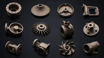
Common examples include automotive engine blocks, brake discs, transmission cases, pump casings, valve bodies, gearbox housings, marine hardware, heavy industrial components, and oil and gas equipment. Sand casting is especially common for parts that are large, heavy, require internal passages, or use ferrous metals (steel, iron).
Is sand casting worth it?
Sand casting is highly cost-effective for prototyping, complex geometries, large parts, ferrous metals (steel, iron), and low-to-medium volumes (up to 1,000–5,000 units). It's a weaker fit when tolerances are tight (±0.05 mm or better), volumes exceed the economic crossover point, surface finish requirements are demanding, or the part is better suited to die casting.
Why is sand casting still used today?
Sand casting works with nearly every castable metal—including steel and iron that die casting cannot handle—and scales from 20 grams to hundreds of tonnes. Minimal tooling investment, flexible geometry, and broad material compatibility make it the most practical option for large castings and ferrous metals where other processes fall short technically or economically.
What type of sand is best for sand casting?
The right sand depends on your part requirements. Green sand (clay-bonded) is most common and cost-effective for general use, offering good reusability and fastest cycle times (6.3–12.5 µm Ra finish, CT7–CT10 tolerances). Resin sand (chemically bonded) offers better dimensional stability and surface finish (3.2 µm Ra achievable, CT7–CT9 tolerances) for more demanding parts, though at higher cost. Sodium silicate (CO₂) sand is preferred for producing sand cores that form internal cavities.