This guide explains how aluminum CNC milling works step-by-step, which variables affect outcomes, how to choose the right alloy and tools, and where the process has limits. By the end, you'll understand why certain design choices cost more, which alloys machine cleanly, and when to specify CNC milling versus alternative manufacturing methods.
Key Takeaways
- Aluminum machines faster and cleaner than steel, producing tight-tolerance parts at lower cost with less tool wear
- 6061-T6 is the default choice for most applications due to excellent machinability and wide availability
- Flute count, helix angle, RPM, and feed rate all affect surface finish — get these wrong and tool life suffers
- Poor chip evacuation is the biggest cause of scrapped parts in aluminum milling, leading to tool welding and surface defects
- Buyers who understand these fundamentals make better sourcing decisions and avoid costly redesigns
What Is Aluminum CNC Milling?
Aluminum CNC milling is a subtractive manufacturing process where computer-controlled rotating cutting tools remove material from a fixed aluminum workpiece to produce precise, complex parts. CNC milling uses multi-tooth rotating tools to create faces, shoulders, profiles, grooves, chamfers, holes, and cavities — achieving defined dimensional tolerances, geometric accuracy, and surface finishes that manual machining cannot deliver consistently.
The process is designed to produce repeatable aluminum components with tight tolerances and complex geometries — including slots, pockets, contours, and threaded features. Unlike CNC turning (which rotates the workpiece and is suited for cylindrical parts like shafts), milling holds the workpiece stationary and moves the cutting tool, making it ideal for non-round, prismatic shapes. That suitability becomes even more pronounced when the material is aluminum.
Why Aluminum Is Widely Milled
Aluminum is one of the most machinable metals available. With a density of just 2.7 g/cm³ — roughly one-third that of steel — aluminum also carries high thermal conductivity, dissipating heat efficiently during cutting.
That combination reduces tool wear and supports higher spindle speeds, making aluminum a first-choice material for CNC milling across automotive, aerospace, industrial equipment, and electronics industries.
What many buyers overlook is that not all aluminum behaves the same under a cutting tool. Alloy chemistry, heat treatment condition, tool selection, and cutting strategy each have direct consequences on cost, quality, and schedule. Procurement teams that treat these decisions as interchangeable risk specifying the wrong alloy or missing chip evacuation requirements — turning a straightforward project into a costly one.
How Aluminum CNC Milling Works
The process follows this sequence: a CAD model is converted into a CAM (Computer-Aided Manufacturing) toolpath program, which drives the CNC machine's spindle and axes. Rotating cutting tools then remove material from the aluminum workpiece. The process progresses from rough material removal (cutting away bulk stock quickly) to semi-finish and finish passes that achieve the final geometry, tolerances, and surface quality.
What goes into the process:
- Aluminum stock (bar, plate, or billet in a specified alloy and temper)
- Cutting tools (end mills, drills, taps)
- Fixturing to secure the workpiece
- Cutting fluid or air blast for chip and heat management
- Verified G-code program defining tool movements, depths, and speeds
How the process is controlled:
Spindle RPM, feed rate, axial depth of cut, and radial engagement are set per the toolpath strategy. The aluminum workpiece is progressively reduced from raw stock to a finished part with defined surface finish, dimensional accuracy, and feature geometry.
Step 1: Workpiece Setup and Fixturing
The workpiece must be rigidly secured before cutting begins — using vises, strap clamps, vacuum tables, or custom fixtures. Any movement under cutting forces causes dimensional errors, chatter marks, or scrapped parts.
Aluminum's low density doesn't mean low cutting forces. Improper fixturing is one of the most common causes of poor outcomes, especially with thin-walled or large-format parts. Even small deflections during cutting show up in the finished surface as out-of-tolerance features or cosmetic defects.
Step 2: Cutting and Material Removal
The spindle accelerates to the programmed RPM, and the end mill engages the aluminum workpiece following the CAM-defined toolpath. The process typically proceeds in phases:
- Roughing passes remove bulk material at higher chip loads with aggressive cuts
- Semi-finish and finish passes follow with tighter tolerances and finer step-overs to hit the required surface quality
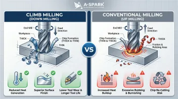
Climb milling vs. conventional milling:
Climb milling (also called down milling) engages the thick part of the chip first, then exits at zero thickness. This reduces heat buildup in the tool, minimizes rubbing, and produces better surface finishes. Conventional milling (up milling) starts at zero chip thickness and exits at maximum — leading to rubbing, heat generation, and chip re-cutting.
Modern CAM strategies like adaptive or dynamic toolpaths maintain consistent cutter load — especially in pockets and corners where traditional strategies force the tool into excess material. In aluminum, sudden engagement spikes cause tool deflection and degrade the finished surface — keeping load consistent is what separates good toolpath strategy from rework.
Step 3: Chip Evacuation and Post-Milling Finishing
Effective chip evacuation is the direct follow-on to good toolpath control. Aluminum chips must be cleared from the cutting zone continuously — re-cutting them causes tool welding, surface degradation, and broken end mills. Chip management strategies include air blast, mist coolant, and flood coolant — with compressed air sufficient for light cuts and flood coolant used for deep pockets or high-volume production.
Post-milling surface treatments:
Common follow-on steps include:
- Anodizing for corrosion resistance and color (Type II anodizing adds approximately 0.0003" per surface)
- Bead blasting for uniform matte texture
- Polishing for reflective surfaces
These treatments must be planned at the design stage since they affect final dimensions and appearance. For example, anodizing thickness grows both outward and inward from the substrate — designers must account for this when specifying critical fits.
Aluminum Alloys and Cutting Tools — What to Know Before You Start
Alloy Selection
Not all aluminum behaves the same under a cutting tool. Alloy chemistry and heat treatment condition directly affect machinability, tool wear, and dimensional stability.
Common aluminum alloys for CNC milling:
| Alloy | Machinability (0-100) | Typical Applications | Notes |
|---|---|---|---|
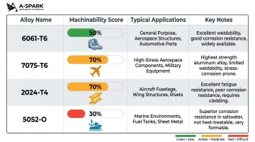
| 6061-T6 | 50% | Structural brackets, enclosures, general machine parts | Excellent balance of machinability, strength, availability; easy to anodize |
| 7075-T6 | 70% | High-strength aerospace components, load-bearing structures | Higher tool wear than 6061; more expensive |
| 2024-T4 | 70% | Aircraft structural parts, high-fatigue applications | Excellent fatigue strength; difficult to anodize |
| 5052-O | 30% | Marine and outdoor parts (corrosion resistance) | Gummy chip behavior; avoid for complex milled geometry |
Understanding temper designations:
Most CNC-milled aluminum is supplied in a specific temper condition that affects internal stress and cutting behavior:
- T6 — solution heat-treated and artificially aged; strong, stable, ideal for tight-tolerance milling
- T651 — T6 plus stress relief by stretching; reduces warping when machining large plates or removing significant material volume
Practical selection rule:
- Default to 6061-T6 for general-purpose industrial parts
- Use 7075-T6 or T651 for maximum strength (at the cost of some machinability)
- Avoid 5xxx series alloys (like 5052 or 5083) for complex milled geometry — if corrosion resistance is required, consider 6061-T6 with anodizing instead
Tool Selection
Once you've selected the right alloy, tool geometry becomes the next critical variable — it determines chip clearance, cutting efficiency, and surface finish.
Key tool parameters:
Flute count:
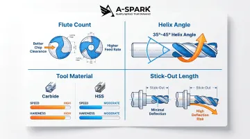
- 2-flute end mills offer the best chip clearance for most aluminum work
- 3-flute tools balance chip clearance with rigidity for deeper cuts
- Single-flute tools work well for router-based setups where spindle RPM is high but machine stiffness is limited
Higher flute counts discourage chip evacuation and should be avoided for roughing non-ferrous materials.
Helix angle:
High-helix tools (35-45°) pull chips upward out of the cut, reducing re-cutting and heat buildup. Use 35-40° for roughing, 45° for finishing or high-efficiency strategies.
Tool material:
- Carbide is the production standard — superior edge retention at high speeds and longer tool life
- HSS (high-speed steel) suits low-volume runs or manual setups where cost is the primary constraint
Minimize tool stick-out:
- Shorter extension below the spindle reduces deflection and chatter — a primary cause of poor surface finish
- Specify stub-length end mills where part geometry allows
Key Factors That Affect Aluminum CNC Milling Quality
Feeds and Speeds
Spindle RPM and feed rate are the primary control variables in CNC milling.
Calculating RPM:
RPM = (SFM × 3.82) / tool diameter
For carbide end mills in aluminum, surface feet per minute (SFM) typically ranges from 600–1,500 SFM depending on alloy and operation.
Calculating feed rate:
Feed rate (inches per minute) = RPM × chip load per tooth × number of flutes
Worked example:
For a 1/4" two-flute carbide end mill in 6061-T6 aluminum at 1,000 SFM:
- RPM = (1,000 × 3.82) / 0.25 = 15,280 RPM
- Chip load per tooth = 0.002" (typical for 1/4" carbide in wrought aluminum)
- Feed rate = 15,280 × 0.002 × 2 = 61 IPM
Critical insight:
Running too slow is as damaging as running too fast. Rubbing instead of cutting generates heat and causes built-up edge (BUE) on the tool — a layer of aluminum that welds to the cutting edge and degrades surface finish.
Machine Stiffness and Toolpath Strategy
CNC machining centers purpose-built for metal are far more rigid than CNC routers repurposed for aluminum. On less rigid machines, depth of cut and radial engagement must be reduced to prevent deflection and vibration from telegraphing into the finished surface.
Adaptive (or dynamic) toolpath strategies improve outcomes on lower-rigidity setups by maintaining consistent cutter engagement through corners and pockets — reducing sudden load changes that cause chatter.
Fixturing Stability and Design for Machinability
Thin walls (below 1 mm) are prone to vibration during cutting. Uniform wall thickness improves cutting stability.
Sharp internal corners cannot be achieved with a rotating tool — design them with a radius matching the tool diameter, or plan for secondary EDM or filing operations.
Practical design tips:
- Avoid razor-sharp internal corners
- Keep pockets at achievable aspect ratios (depth-to-width)
- Specify corner radii in the CAD model
These simple choices reduce machining time and cost without affecting function.
Quality Assurance for Industrial and Regulated Applications
For automotive, aerospace, and medical parts, milled components are typically inspected with CMM (coordinate measuring machines) or optical gauging against the CAD nominal dimensions. Certifications like IATF 16949 (automotive quality management) and ISO 9001:2015 establish documented process controls that ensure repeatable part quality across production runs.
A-SPARK Manufacturing, for example, holds IATF 16949 certification and provides PPAP and dimensional reporting as standard deliverables. Their Bac Ninh facility integrates CNC machining with in-house die casting, surface treatment, and assembly — covering the full documentation chain that automotive and industrial customers require.
Common Mistakes and When Aluminum CNC Milling Isn't the Right Choice
Frequent Operational Mistakes
- Wrong alloy selection: 5xxx series alloys (especially 5052) are gummy and prone to chip adhesion — avoid them for complex milled parts.
- Overly conservative feeds and speeds: Slow feeds with high spindle RPM cause rubbing, heat buildup, and built-up edge. Conventional milling worsens this by starting at zero chip thickness, producing poor finishes and premature tool failure.
- Too many flutes: High flute counts leave insufficient chip clearance in aluminum, causing chip packing and re-welding.
- Poor chip evacuation: In deep pockets or enclosed features, chips must be cleared continuously — re-cutting them destroys surface finish and breaks tools.
Where Teams Misuse or Over-Specify the Process
Operational errors are one thing — but sometimes the bigger problem is using CNC milling when a different process would perform better and cost less.
- Tolerances tighter than ±0.005 mm: Grinding or EDM achieves these more economically than milling.
- High-volume simple profiles: Parts suited to extrusion or die casting at volume — CNC milling is flexible, but not the most cost-effective option at scale.
- Repeated design revisions: Each change requires new toolpaths, setups, and sometimes new fixtures, making iterative prototyping expensive past initial validation.
When Alternative Processes Are Better Suited
- Aluminum die casting: More economical at medium-to-high volumes for complex net-shape parts, with post-machining reserved for critical features only.
- Aluminum extrusion: The better option for long, uniform cross-sections where milling would remove excessive material.
- Sheet metal fabrication: Well-suited to enclosures and brackets that don't require bulk material removal.
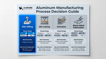
Process selection should be driven by volume, geometric complexity, tolerance requirements, and surface finish — not default preference for CNC milling.
Frequently Asked Questions
Can you CNC aluminium?
Yes. Aluminum is one of the most CNC-machinable metals available — it cuts cleanly, allows high spindle speeds, produces good surface finishes, and causes less tool wear than steel, making it a first-choice material across industries.
What is the best aluminium for CNC milling?
6061-T6 is the standard starting point for most applications due to excellent machinability, availability, and strength. Use 7075-T6 or T651 for high-strength applications. Avoid 5xxx series alloys (such as 5052) for complex milled geometry due to gummy chip behavior.
What is the best CNC bit for cutting aluminum?
2-flute carbide end mills with a high-helix angle (35-45°) are the most reliable general-purpose choice. Single-flute tools work well for high-RPM router setups. Minimize tool stick-out to reduce deflection.
Can you cut aluminum with a CNC router?
Yes, but with important caveats: router rigidity is lower than a machining center, so depths of cut and feed rates must be reduced. Single-flute carbide end mills, proper lubrication, and adaptive toolpath strategies significantly improve results.
What speed should you mill aluminum at?
Carbide end mills in aluminum typically run at 600–1,500 SFM, or roughly 16,000–24,000 RPM for a 1/4" end mill. Always calculate feed rate from chip load per tooth (0.001"–0.004" for a 1/4" carbide 2-flute) — guessing in either direction causes premature tool failure.
What materials cannot be used when CNC milling?
Most metals, plastics, and composites can be CNC milled, but some require process adaptations: hardened steels above 65 HRC need specialized tooling; rubber and foam tend to deflect rather than shear cleanly; and highly abrasive composites like carbon fiber demand diamond-coated tools and dedicated dust management. None of these are standard aluminum milling setups.