Introduction
Aluminum has become the dominant material in precision CNC machining for a simple reason: it delivers an unusually strong set of properties — light weight, structural strength, easy machinability, and natural corrosion resistance. Across industries from automotive and electric vehicles to aerospace, electronics, and industrial equipment, aluminum is the first-choice metal when engineers need to reduce weight without compromising structural integrity.
This advantage isn't theoretical. Aluminum 6061-T6 weighs approximately 2.9 times less than carbon steel — a critical factor as lightweighting drives fuel efficiency in automotive applications and enables longer flight ranges in aerospace. But aluminum's real edge emerges in the machine shop: it requires 2-4 times less cutting force than steel, allowing faster spindle speeds, shorter cycle times, and lower tool wear.
Engineers and procurement teams who get alloy selection, tooling strategy, and design optimization right can cut both cost and lead time. This guide covers the decisions that matter most — from choosing between 6061, 7075, and 5052 to managing challenges like built-up edge and thermal expansion.
Key Takeaways
- Aluminum machines significantly faster than steel with less tool wear, making it ideal for prototyping and high-volume production
- Alloy choice (6061, 7075, 5052) and temper (T6, T651) directly shape machinability, structural performance, and unit cost
- Milling, turning, drilling, and tapping each serve distinct geometries and must match part requirements
- Common challenges — built-up edge, thermal expansion, thin-wall vibration — are manageable with the right tooling and parameters
- Early DFM input, realistic tolerances, and clean CAD files are the fastest way to cut cost and lead time
Why Aluminum Is the Preferred Metal for Precision CNC Machining
Strength-to-Weight Ratio Drives Lightweighting Trends
Aluminum 6061-T6's density of 2.70 g/cc versus carbon steel's 7.85 g/cm³ creates a weight ratio of nearly 3:1 for equivalent-volume components. This weight advantage translates directly to performance gains: reduced vehicle mass improves fuel economy and extends EV battery range, while aerospace applications achieve longer flight distances and higher payload capacity.
Structural integrity stays high despite the weight savings. High-strength 7075-T6 aluminum delivers 572 MPa ultimate tensile strength — comparable to many mild steels — at one-third the weight. This makes aluminum the logical choice for load-bearing automotive structural brackets, aerospace frames, and industrial equipment housings where every gram matters.
Machinability Advantage Cuts Cycle Time and Cost
Sandvik Coromant's material data quantifies aluminum's machinability edge: specific cutting force of 350-700 N/mm² versus 1,400-3,100 N/mm² for steel. This 2-4x force reduction permits:
- Higher spindle speeds without excessive heat generation
- Faster feed rates that reduce cycle time per part
- Lower tool wear that extends cutting edge life
- Reduced power consumption and machine stress
Standard carbide tooling for aluminum operates at cutting speeds up to 1,000 m/min (3,280 SFM), with high-speed machining (HSM) configurations reaching 5,000 m/min (16,400 SFM). Steel, by comparison, typically machines at 150-250 m/min. This speed differential translates directly to lower per-part cost, especially critical for high-volume OEM production.
Natural Corrosion Protection and Finishing Versatility
Aluminum's surface atoms spontaneously oxidize, forming a passive aluminum oxide (Al₂O₃) layer 1-10 nanometers thick that prevents further corrosion. This passive layer reduces coating requirements for many environments, though alloy composition determines how far that protection extends. Where additional performance is needed, aluminum readily accepts a wide range of surface treatments:
- Anodizing — adds corrosion resistance, enables color options, produces matte or glossy finishes
- Bead blasting — creates uniform matte texture, removes machining marks
- Powder coating — provides durable color finish for industrial or consumer applications
- Polishing — delivers reflective surfaces for aesthetics or optical applications
Manufacturers with in-house surface treatment capabilities can complete all finishing stages under one roof, cutting supplier handoffs and compressing lead times for fully finished parts.
Choosing the Right Aluminum Alloy for Your Application
Wrought vs. Cast Alloys: Why Wrought Dominates CNC
Wrought alloys — shaped in solid state through rolling, extrusion, or forging — dominate precision CNC machining due to superior dimensional consistency, better surface finish, and lower tool wear compared to cast alloys. By contrast, cast aluminum is more commonly used in die casting processes where complex geometries are formed in molds rather than machined from solid stock.
6061: The Balanced Workhorse
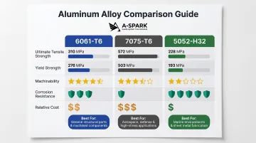
6061-T6 is the most widely specified CNC aluminum alloy, delivering balanced strength, excellent machinability, good corrosion resistance, and low cost. With 310 MPa (45,000 psi) ultimate tensile strength and 276 MPa (40,000 psi) yield strength, it handles moderate structural loads while remaining easy to machine.
Common applications include:
- Automotive structural brackets and mounting plates
- Electronics enclosures and frames
- Industrial equipment housings
- General-purpose brackets and fixtures
6061 is almost always supplied in T6 temper for CNC work, meaning it has been solution heat-treated and artificially aged for maximum strength.
7075: High-Strength for Demanding Applications
7075-T6 provides nearly 1.8x the tensile strength of 6061 (572 MPa / 83,000 psi ultimate tensile strength) with superior fatigue resistance. This makes it essential for aerospace structural components, defense applications, and motorsport parts where strength-to-weight ratio is the deciding factor.
Those gains come with trade-offs:
- Higher tool wear during machining requires tighter parameter control
- Approximately 1.5-2x material cost premium over 6061
- Lower corrosion resistance than 6061
- Machinability rating of approximately 70% versus 6061's excellent rating
Despite these challenges, 7075 remains the correct choice when maximum strength justifies higher machining difficulty and cost.
5052: Corrosion-Critical Applications
When corrosion resistance matters more than raw strength, 5052 is the alloy to specify. Non-heat-treatable and strain-hardened with magnesium as the primary alloying element, it outperforms 6061 and 7075 in marine, outdoor, and harsh-environment applications.
Properties include:
- 228 MPa (33,000 psi) ultimate tensile strength — lowest of the three alloys
- Superior resistance to seawater and salt spray
- Clean machining characteristics
- Strength achieved through strain hardening (H-temper) rather than heat treatment
Specify 5052-H32 for boat components, marine enclosures, chemical processing equipment, and outdoor installations where corrosion outweighs strength requirements.
T6 vs. T651: Stress Relief for Heavy Stock Removal
T6 temper indicates solution heat treatment followed by artificial aging for maximum strength. T651 adds a controlled 1.5-3% permanent stretch after solution heat treatment and before aging, which relieves residual internal stresses from quenching.
For CNC machining of plate stock, T651 is strongly preferred because it reduces warping and distortion during heavy material removal. One industry source reports machining distortion reduced by approximately 60% with T651 versus T6.
Always specify T651 for thick plates that will undergo aggressive roughing operations or deep pocket milling.
Alloy Comparison Table
| Property | 6061-T6 | 7075-T6 | 5052-H32 |
|---|---|---|---|
| Ultimate Tensile Strength | 310 MPa / 45,000 psi | 572 MPa / 83,000 psi | 228 MPa / 33,000 psi |
| Yield Strength | 276 MPa / 40,000 psi | 503 MPa / 73,000 psi | 193 MPa / 28,000 psi |
| Machinability | Excellent | Good (70% rating) | Good |
| Corrosion Resistance | Good | Fair | Excellent (marine) |
| Relative Cost | Low (baseline) | High (1.5-2x) | Moderate |
| Typical Applications | Brackets, housings, frames | Aerospace, motorsport | Marine, outdoor equipment |
Core CNC Machining Processes for Aluminum Parts
CNC Milling
Milling is the backbone of precision aluminum machining. A rotating cutter removes material layer by layer from a fixed workpiece, creating flat surfaces, deep pockets, complex contours, and intricate geometries.
3-axis to 5-axis configurations define capability range:
- 3-axis mills handle prismatic parts with features accessible from top and sides — plates, brackets, simple housings
- 4-axis mills add rotational capability for cylindrical features without repositioning
- 5-axis mills eliminate multiple setups and enable undercuts, compound angles, and complex organic shapes in a single operation
High-performance 5-axis machines for aluminum typically run spindles up to 60,000 RPM optimized for high-speed cutting (HSC), achieving positional accuracy under 15 µm and surface finishes of Ra < 0.1 µm with proper tooling and parameters.
For aerospace structural components and automotive lightweighting applications requiring compound angles, 5-axis machining reduces fixture complexity, improves dimensional consistency by eliminating part repositioning, and shortens overall cycle time.
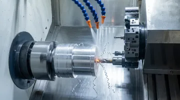
CNC Turning
Turning machines rotate aluminum stock while a stationary tool shapes outer and inner diameters. Applications include shafts, bushings, connectors, fittings, and threaded components.
Modern CNC turning centers equipped with live (driven) tooling combine turning, milling, drilling, and tapping in a single setup. For aluminum rotational parts, this eliminates part transfers between machines and improves concentricity. Complex features are completed without re-fixturing:
- Off-center holes and cross-holes
- Flats and slots
- Internal and external threads
A-SPARK Manufacturing operates 30 sets of CNC turning machines with 50mm diameter capability alongside 15 sets of multi-axis milling machines, enabling comprehensive machining of aluminum components from raw stock to finished part.
Drilling, Boring, and Tapping
These operations create and refine internal features. Each serves a distinct purpose in achieving final hole geometry:
- Drilling produces the initial hole at specified diameter and depth
- Boring refines hole diameter to tight tolerances, correcting position and roundness
- Tapping cuts internal threads to accept fasteners or fittings
Aluminum's tendency to tear rather than cut cleanly under poor feed rates or dull tooling makes accurate setup critical. Chip welding and broken taps are common failures in under-optimized operations. Proper coolant application and sharp cutting edges prevent these issues.
Surface Finishing After Machining
Post-machining finishing options for aluminum include:
- Anodizing — electrochemical process that thickens the oxide layer, adds corrosion resistance, enables color options (clear, black, gold, red), and produces matte or glossy surfaces
- Bead blasting — uniform matte texture that removes machining marks and prepares surfaces for coating
- Powder coating — durable color finish for industrial or consumer applications, applied electrostatically then cured
- Polishing — mechanical or chemical process creating reflective surfaces for aesthetics or optical applications
Integrated surface treatment facilities eliminate inter-supplier handoffs and compress lead time. A-SPARK's in-house capabilities span die casting, CNC machining, and finishing — allowing automotive, industrial, and electronics customers to consolidate their supply chain under a single partner.
Tooling, Speeds, and Cutting Strategies for Precision Results
Tool Selection: Carbide, Flute Count, and Geometry
Carbide end mills are the production standard for aluminum, maintaining sharp cutting edges at high speeds while resisting heat buildup better than HSS (high-speed steel).
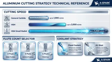
Flute count affects chip clearance and material removal rate:
- 2-flute end mills maximize chip clearance for deep pockets and slots
- 3-flute end mills balance speed and chip load for general roughing and finishing
- 4-flute end mills suit finishing passes where surface quality matters more than chip volume
Kennametal's aluminum end mill product line shows 3-flute configurations as most prevalent (190 out of 274 products), pointing to a production preference for 3-flute geometry and higher material removal rates.
High-helix geometry (typically 45 degrees) pulls chips upward and away from the cut, preventing recutting and protecting surface finish. Harvey Tool offers 2-flute high-helix end mills at 45-degree helix specifically for aluminum alloys.
Speeds and Feeds: Run Aluminum Fast
ISCAR's cutting speed framework for aluminum with carbide tooling:
| Tool Category | Cutting Speed |
|---|---|
| General-duty solid carbide | Up to 1,000 m/min (3,280 SFM) |
| HSM with aggressive parameters | Up to 2,000 m/min (6,560 SFM) |
| HSM with small radial engagement | Up to 5,000 m/min (16,400 SFM) |
High-speed machining typically requires 30,000 RPM or more and demands tool balancing per ISO 16084. The core principle: aluminum machines best at higher spindle speeds with consistent feed pressure. Running too slow causes the tool to rub rather than cut, generating heat and accelerating wear.
Coolant and Chip Evacuation Strategy
Sandvik Coromant recommends cutting fluid always be used when machining aluminum to prevent smearing on insert edges and improve surface finish. Recommended concentration: 5% for silicon content below 8% (covers 6061, 7075, and 5052).
Flood coolant or a strong directed air blast serves two critical functions:
- Prevents heat buildup that leads to built-up edge on the cutting face
- Clears chips before they recut — one of the most common causes of poor surface finish and premature tool failure
- Allows higher feed rates without sacrificing part quality
For aluminum, pushing chip evacuation harder delivers better results than slowing the spindle down.
Common Challenges in Precision Aluminum CNC Machining
Built-Up Edge (BUE)
Built-up edge occurs when aluminum adheres to the cutting tool edge due to material affinity, insufficient cutting speed, or inadequate chip evacuation. This degrades surface finish and causes dimensional inaccuracy.
Prevention strategies:
- Use sharp, polished carbide tools with positive rake angles
- Apply adequate coolant to reduce heat at the cutting edge
- Maintain correct chip load — neither too light nor too heavy
- Consider PCD (polycrystalline diamond) inserts for high-volume production
Uncoated polished carbide and DLC (diamond-like carbon) coated tools remain the go-to choices for aluminum because they minimize material adhesion and preserve edge sharpness longer than standard coatings.
Thermal Expansion
Heat buildup at the cutting edge compounds these risks on a second front: dimensional drift. Aluminum's coefficient of thermal expansion (CTE) is approximately 23.6 × 10⁻⁶/°C — roughly 2x that of carbon steel (11.7 × 10⁻⁶/°C). For a 300mm aluminum part with a 10°C temperature change, thermal growth reaches approximately 0.071mm — enough to push tight-tolerance features out of specification.
Mitigation strategies:
- Use staged machining: rough passes followed by finish passes after thermal stabilization
- Apply consistent coolant throughout the operation
- Avoid continuous heavy cuts that generate excessive heat
- Inspect parts at controlled temperatures with adequate stabilization time
- Factor thermal growth into GD&T specifications
Thin-Wall Vibration and Fixturing
Walls under approximately 1mm thickness tend to chatter, deflect, and produce poor surface finish — particularly on features with height-to-thickness ratios above 4:1, where the cutting force has little material mass to work against.
Harvey Performance Company recommends a stepped-down approach: divide total wall height into manageable axial depths while working each side to maintain a wide cross-section of support stock as long as possible.
Additional strategies:
- Design stable fixturing that supports the workpiece without inducing stress
- Use High Efficiency Milling (HEM) toolpaths with low radial depth of cut (RDOC) and high axial depth of cut (ADOC)
- Reduce feed rates and depth of cut on vulnerable features
- Consider necked-down tooling for depths greater than 3x diameter
- Progressively decrease radial engagement as walls become thinner
Design Tips for Better Aluminum CNC Parts
Match Internal Corner Radii to End Mill Geometry
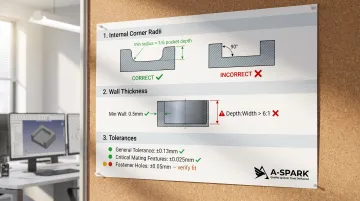
Sharp internal corners cannot be machined by round tools without secondary operations or very small, slow cutters. Protolabs states milling cutters go down to 0.040 in. (1mm) diameter, meaning internal corner radii will be minimum 0.020 in. (0.5mm) — half the cutter diameter.
General DFM rule: internal pocket corner radius should be no less than 1/6 the pocket depth. Specifying larger corner radii allows the use of larger, more rigid cutters, which improves surface finish, reduces chatter, lowers cycle time, and extends tool life.
Designing internal radii to match standard end mill sizes (typically with 10-15% clearance beyond tool radius) avoids expensive workarounds.
Wall Thickness and Cross-Section Uniformity
Sudden changes in wall thickness trap heat and stress during machining, increasing the risk of warping and poor finish.
Guidelines:
- Minimum wall thickness: approximately 0.020 in. (0.5mm) on material adjacent to features
- Feature depth-to-width ratio: keep depth less than 6x the feature width for slots and pockets
- Use gradual transitions in cross-section rather than abrupt steps
- Maintain uniform wall thickness where possible to distribute thermal expansion evenly
Aluminum's lower rigidity compared to steel makes conservative wall thickness specs essential — particularly for thin-walled enclosures and deep pockets common in electronics and automotive applications.
File Quality and Tolerance Specification
Getting the geometry right on-screen is only half the job. How you export and specify that geometry determines whether the shop floor produces what you designed.
Preferred CAD formats:
- STEP (.stp/.step) — universal standard preserving 3D solid geometry with high translation accuracy
- IGES — widely accepted but prone to surface gaps with complex geometry
- Native formats — SolidWorks, Fusion 360, Inventor files accepted by most CNC shops
STEP files (particularly AP214) reduce the risk of missing features or geometry corruption. When exporting from SolidWorks, AP214 is generally preferred over AP203 as it supports additional product data.
Tolerance best practice:
Over-tolerancing non-critical features drives up inspection time and cost. Specify only the tolerances that are functionally necessary. For example:
- General machining tolerance: ±0.13mm (±0.005 in.)
- Critical mating surfaces: ±0.025mm (±0.001 in.)
- Hole locations for fasteners: ±0.05mm (±0.002 in.)
A-SPARK Manufacturing provides DFM review as part of the quoting process — catching tolerance conflicts, feature geometry issues, and file errors before production begins, which cuts scrap rates and compresses development cycles.
Frequently Asked Questions
What is the best aluminum alloy for CNC?
6061-T6 is the best all-around choice for most applications due to its balance of machinability, strength, corrosion resistance, and cost. It handles moderate structural loads while remaining easy to machine and affordable. 7075-T6 is preferred when maximum strength is needed and higher cost plus machining difficulty are acceptable trade-offs.
How hard is it to machine 7075 aluminum?
7075 is considerably harder to machine than 6061 — it causes more tool wear, requires tighter control over feeds and speeds, and is prone to built-up edge. However, with proper carbide tooling, adequate coolant, and correct parameters, it produces precise, high-strength parts suitable for aerospace and motorsport applications.
What's the difference between aluminum 6061-T6 and regular aluminum 6061?
The T6 designation indicates the alloy has been solution heat-treated and artificially aged, which substantially increases its yield strength and hardness compared to annealed (non-T6) condition. T6 is the standard temper specified for CNC machining applications requiring maximum strength and dimensional stability.
What is the recommended SFM for 6061 aluminum?
Standard carbide tooling for 6061 aluminum supports cutting speeds up to 1,000 m/min (approximately 3,280 SFM). HSM-optimized setups with small radial engagement can reach 5,000 m/min (16,400 SFM). This range is far higher than steel, reflecting aluminum's superior machinability and the advantage of running at aggressive cutting speeds.
How expensive is it to CNC aluminum?
Aluminum is generally less expensive to CNC machine than steel or titanium — faster cycle times and lower tool wear reduce per-part costs. That said, alloy choice (6061 vs. 7075), tight tolerances, and surface finishing requirements can meaningfully affect pricing. Volume and part complexity are the other main cost drivers.