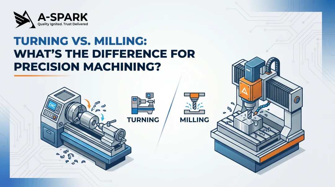
Both CNC turning and CNC milling are subtractive, computer-numerically controlled processes that remove material to create precision components. However, they excel at fundamentally different part geometries, feature sets, and production scenarios. CNC turning rotates the workpiece against a stationary cutting tool, making it ideal for cylindrical components. CNC milling rotates a multi-point cutting tool against a fixed workpiece, optimized for flat faces, pockets, and complex 3D profiles.
This article covers the part types each process handles best, key decision factors, compatible materials, achievable tolerances and surface finishes, and industry applications — plus how modern hybrid capabilities are blurring the traditional boundaries between turning and milling.
Key Takeaways
- CNC turning produces cylindrical, rotationally symmetric parts — shafts, bushings, flanges, and pins — by rotating the workpiece against a stationary cutting tool
- CNC milling creates prismatic, flat, or complex-geometry parts (housings, brackets, gears, manifolds) by rotating a multi-edge cutting tool against a fixed workpiece
- Turn-mill centers with live tooling complete hybrid parts in a single setup, cutting out secondary operations for most turned components
- Both processes hold tolerances from ±0.005" (standard) to ±0.0001" (ultra-precision) and surface finishes down to Ra 0.25 µm
- Select based on part geometry first: cylindrical = turning; prismatic = milling; hybrid geometries benefit from multi-axis or turn-mill equipment
CNC Turning vs. CNC Milling: A Quick Overview
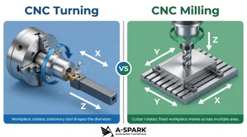
The fundamental operational difference defines everything. In CNC turning, the workpiece rotates on a lathe or turning center while a stationary single-point cutting tool removes material along X and Z axes. In CNC milling, the cutting tool rotates (a multi-edge end mill or face mill) while the workpiece remains fixed or repositioned along X, Y, and Z axes. Both are computer-numerically controlled and subtractive, but this kinematic difference determines which geometries each process handles efficiently.
Each process has a natural output suited to its motion:
- Turning generates cylindrical or round forms from bar stock or tube stock — parts defined by rotation around a central axis
- Milling generates prismatic parts with flat faces, slots, holes, contours, and complex 3D profiles from billet blocks or plate stock
For design engineers and procurement teams, selecting the wrong process drives real cost penalties: higher tooling costs, more setups, longer lead times, and tolerance risk. Machining a cylindrical shaft on a milling machine, for instance, requires multiple setups and complex fixturing — a lathe completes the same part in a single rotation.
The reverse is equally true. Milling flat faces or pockets on a conventional lathe without live tooling means transferring the part to a separate machine, adding handling, fixturing cost, and tolerance stack-up risk.
These process boundaries matter beyond individual parts — they shape how manufacturers invest in equipment and capacity. The global precision machining market reached USD $123.54 billion in 2025 and is projected to reach USD $228.75 billion by 2033 at an 8.1% CAGR, with CNC operations accounting for 78.9% of the total, according to Grand View Research. Within CNC, milling holds the largest type-segment share, followed by turning — though real-world overlap between the two is growing as turn-mill technology advances.
What Parts Can Be Made by CNC Turning?
Characteristics of Ideal CNC-Turned Parts
CNC turning is best suited for parts with rotational symmetry around a central axis — meaning the part's overall shape can be generated by rotating a 2D profile. The dominant geometry must be cylindrical or round, typically starting from bar or tube stock. While some asymmetric features such as flats, cross-holes, or radial slots can be added with live tooling (discussed below), the core form must be round.
Ideal candidates for turning:
- External cylindrical surfaces (shafts, pins, sleeves)
- Internal cylindrical bores (bushings, tubes, collars)
- Tapered profiles and conical sections
- Grooves, threads, and radial features
- Face features perpendicular to the rotation axis
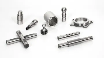
Common Part Types Produced by CNC Turning
The most common part families produced on a CNC lathe share a need for tight diameter control, concentricity, and repeatable surface finish:
- Shafts and axles — Transmit rotational motion or support rotating assemblies; require precise diameters and concentricity
- Bushings and sleeves — Provide wear resistance and bore alignment; demand uniform inner and outer diameters
- Flanges and couplings — Connect pipes, valves, or power transmission shafts; need accurate bolt patterns and flat sealing faces
- Pins, dowels, and rollers — Handle alignment, pivoting, or conveyor functions; tight diameter tolerances are non-negotiable
- Nozzles and fittings — Control fluid or gas flow; rely on precise internal profiles and thread forms
- Threaded fasteners and studs — Standard and custom thread forms for structural assembly applications
Industry-Specific Examples of CNC-Turned Parts
| Industry | Common Turned Parts |
|---|---|
| Automotive | Crankshafts, camshafts, axle shafts, drive shafts, pulleys, pistons |
| Aerospace | Hydraulic fittings, spacers, bushings, landing gear components |
| Medical | Bone screws, dental implants, surgical instrument handles |
| Oil & Gas | Valve stems, couplings, pipe fittings, downhole tool components |
| Electronics | Connectors, contact pins, terminals, precision standoffs |
Complex Features Achievable on a Turning Center
Modern CNC lathes with live tooling can add milled features during the same setup, eliminating secondary operations. Live tooling systems use motor-driven tools mounted in the turret that can mill, drill, or tap while the workpiece continues to rotate or is indexed to specific positions.
Features enabled by live tooling:
- Cross-drilled and off-axis holes, including tapped holes
- Flats and slots milled directly into cylindrical bodies
- Hexagonal or square sections on otherwise round parts
- Keyways and spline cuts
Multi-turret and sub-spindle configurations take this further, allowing complex turned parts to finish in a single cycle. That means less part handling, lower work-in-process inventory, and tighter control over dimensional consistency across the run.
Tolerances and Surface Finish in CNC Turning
Understanding what live tooling and multi-spindle setups can achieve makes the precision question natural: what tolerances and surface finishes does CNC turning actually deliver?
Protolabs specifies a typical CNC machining tolerance of ±0.005" (0.13 mm) for prototype and production work. Protocase defines three precision tiers: Standard at ±0.005", Premium between ±0.005" and ±0.001", and Ultra between ±0.001" and ±0.0001".
Surface finish benchmarks:
RapidDirect identifies Ra 3.2 µm (125 µin) as the baseline finish for CNC turning and Ra 0.8 µm (32 µin) as a high-grade finish achievable with fine turning. Sandvik Coromant data shows that at a feed of 0.20 mm/rev with a standard 0.8 mm nose radius insert, surface finish is approximately Ra 1.25 µm (50 µin); with a wiper insert at the same parameters, finish improves to Ra 0.35 µm (14 µin) — roughly twice the quality at the same feed rate, directly improving productivity without sacrificing finish.
In practice, CNC turning delivers ±0.001" to ±0.005" tolerances and surface finishes down to 32 µin on modern lathes, sufficient for most fit-and-function requirements without post-process grinding. Tighter tolerances down to ±0.0005" are achievable with optimized setups.
What Parts Can Be Made by CNC Milling?
Characteristics of Ideal CNC-Milled Parts
CNC milling is optimized for prismatic parts — those with predominantly flat faces, angles, slots, pockets, or complex 3D contoured surfaces — and for parts that cannot be defined by simple rotation around an axis. The workpiece is clamped in a fixture and the rotating multi-flute cutter removes material along programmed X, Y, Z (and rotational) paths.
Ideal candidates for milling:
- Flat surfaces and angled planes
- Pockets, slots, and recesses
- Complex 3D sculptured surfaces
- Multi-plane features requiring different tool access angles
- Internal cavities and mold profiles
- Gear teeth and splines (when not generated by hobbing)
Common Part Types Produced by CNC Milling
Primary part families include:
- Enclosures and housings — Electronics, motors, gearboxes; require precise mounting holes and sealing surfaces
- Structural brackets and plates — Aerospace frames, automotive mounts; demand high strength-to-weight ratios
- Gear blanks and gear profiles — Precision tooth forms for power transmission
- Mold and die cavities — Injection molds, die casting dies; require complex 3D surfaces and tight tolerances
- Heat sinks — Electronics cooling; feature intricate fin arrays and mounting patterns
- Manifolds — Fluid distribution; require internal passages and port profiles
- Impellers — Pumps and turbines; demand complex curved blades
- Valve bodies — Oil & gas, hydraulic systems; need precise internal passages and sealing surfaces
- Custom fixtures — Production tooling and inspection gauges
- Aerospace structural frames or ribs — High-strength aluminum or titanium components with weight-optimized pockets
The part families above span a wide range of geometric complexity — and how that complexity is handled depends heavily on how many axes the machine operates simultaneously.
How Multi-Axis Capability Expands Part Complexity
The progression from 3-axis to 5-axis milling dramatically expands geometric capability and reduces setup count:
| Axis Config | Capability | Setup Impact | Example Parts |
|---|---|---|---|
| 3-axis | Linear X/Y/Z; one side per fixture setup | 6 setups for 6 sides; higher fixture cost | Planar profiles, drillings, threaded holes |
| 4-axis | Adds A-axis (rotation around X); machine 4 sides in one setup | Reduces fixtures (example: ~$1,100 vs. ~$2,000 for 3-axis equivalent) | Cam lobes, helixes, angled features |
| 5-axis | Adds second rotary axis; simultaneous 5-axis movement | Maximum flexibility, single setup for compound angles | Complex curved 3D surfaces, compound-angle features |
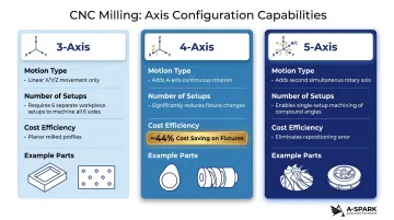
Source: CloudNC
The 4-axis example demonstrates a 44% fixture cost reduction compared to 3-axis on the same part, confirming that multi-axis investment pays back through setup consolidation, not just geometric capability.
For aerospace and medical parts requiring compound angles and tight inter-feature tolerances, 5-axis machining goes further: fewer setups mean lower cost and better geometric accuracy, since each additional setup introduces tolerance stack-up between features.
DFM Considerations for Milled Parts
Design-for-manufacturability rules directly impact cycle time and cost:
| DFM Parameter | Recommended | Feasible/Minimum | Why It Matters |
|---|---|---|---|
| Internal corner radius | 1/3 × cavity depth | Larger is better | Allows standard-diameter end mills; minimizes tool changes |
| Cavity depth | 4× cavity width | Up to 30:1 with specialty tooling | Prevents tool deflection and chatter |
| Wall thickness (metal) | 0.8 mm | 0.5 mm minimum | Avoids vibration during machining |
| Wall thickness (plastic) | 1.5 mm | 1.0 mm minimum | Prevents warping and breakage |
| Hole depth | 4× nominal diameter | 10× typical, 40× feasible | Deeper holes require specialty drills and increase cycle time |
Source: Hubs/Protolabs Network
Two rules reduce cost most reliably:
- Keep internal corner radii at least 1/4 of pocket depth to accommodate standard-diameter end mills
- Standardize feature radii across the part to eliminate unnecessary tool changes and shorten cycle time
Tolerances and Surface Finish in CNC Milling
Standard tolerances:
Hubs specifies a typical CNC milling tolerance of ±0.1 mm (±0.004") with a feasible precision of ±0.02 mm, referencing ISO 2768 medium or fine as standard when no specific tolerances are provided. DMG MORI states modern CNC milling machines achieve tolerances in the micrometer range.
Surface finish:
RapidDirect confirms Ra 3.2 µm (125 µin) as the baseline milling finish and Ra 1.6 µm (63 µin) as standard precision, achievable with optimized CNC parameters.
Important: Surface finish and tolerance requirements directly drive machining time and cost. Designers should specify only the precision levels genuinely required by fit and function — over-specifying adds cost without adding value.
How to Decide: Turning or Milling for Your Part?
Geometry is the primary decision driver. If the part's dominant form is cylindrical, round, or rotationally symmetric and can be produced from bar or tube stock, CNC turning is typically the more efficient and cost-effective choice. If the part has predominantly flat faces, asymmetric profiles, complex internal pockets, or features on multiple planes, CNC milling is the appropriate process.
Key decision factors:
Part geometry — Rotational symmetry favors turning; prismatic or multi-face geometry favors milling.
Production volume and cycle time — Turning generally offers faster cycle times for high-volume cylindrical parts due to the continuous rotational cut. Milling is more flexible for low-to-medium volumes and prototype runs where geometry varies widely.
Feature complexity and hybrid machining — A turning center with live tooling handles flat faces, cross-holes, and off-axis features in one setup, removing the need to transfer parts to a mill. Conversely, a machining center with boring capability can eliminate a secondary lathe operation when a prismatic part needs a precision-bored hole or turned boss.
Cost implications — Tooling costs, number of setups, material starting form (bar stock vs. billet block), and machine utilization all factor into per-part cost. Engaging your manufacturing partner early in the design phase optimizes process selection before tooling is committed, reducing cost and shortening the path from design to production.
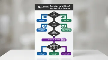
That last point — hybrid machining — is where the decision becomes less binary. The PMPA notes that modern turn-mill machines with Y-axis capability enable shops to "drop parts complete," performing milling operations like slots and bolt holes in a single setup, removing the need to choose between processes for complex geometries.
Materials Compatible with CNC Turning and Milling
Both CNC turning and milling support a wide range of metals, plastics, and composites. However, material properties such as hardness, thermal conductivity, and chip formation behavior affect both process selection and tooling choices.
Metals
Common metals machined by both processes:
Aluminum alloys — Lightweight, excellent machinability, widely used in automotive, aerospace, and electronics. Sandvik classifies aluminum in ISO Group N with specific cutting force of 350–700 N/mm² (easiest to machine). Best cut with PCD for high-silicon alloys; fine-grained uncoated carbide for low-silicon grades.
Brass and copper — Free-cutting behavior with minimal tool wear; used in fittings, electrical components, and decorative applications. Also ISO Group N with similar low cutting forces.
Carbon steel and alloy steels — Structural and mechanical applications. ISO Group P with cutting force 1,400–3,100 N/mm². Coated carbide inserts work best; sharp geometries for low-carbon grades.
Stainless steel — Corrosion resistance for medical, food processing, and marine applications. Austenitic and duplex grades fall in ISO Group M with cutting force 1,800–2,850 N/mm². Difficult to machine due to work-hardening; requires sharp-edge carbide or cermet for finishing.
Titanium — Aerospace and medical applications; more challenging to machine. ISO Group S with cutting force 1,300–3,100 N/mm². Carbide inserts are the standard choice. Critical warning: Do NOT use ceramic inserts on titanium due to chemical reactivity at elevated cutting speeds, per Sandvik Coromant.
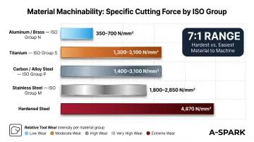
Material machinability hierarchy:
Sandvik's ISO classification reveals a nearly 7:1 range in specific cutting force between aluminum (350 N/mm²) and hardened steel (4,870 N/mm²), translating directly to tool wear rates, cutting speeds, and per-part cost.
Engineering Plastics
CNC-machinable plastics include:
- Acetal (POM/Delrin) — Excellent machinability; used in bearings, bushings, gears, precision parts, fuel system components
- Nylon — Medium machinability; gears, bushings, gaskets, electrical connectors, pulleys
- Polycarbonate — Housings, guards, transparent components requiring impact resistance
- PEEK — High-performance material suited for aerospace seals, medical implants, oil & gas valve seats, semiconductor equipment; requires specialized carbide tooling due to its hardness and abrasiveness
- UHMW — Low-friction applications, wear strips, bearings
Curbell Plastics specifies that unreinforced thermoplastics can be machined with HSS tools, while glass-reinforced materials require carbide-tipped tools (C-2 grade inserts recommended for turning).
Industry Applications: Where CNC Machined Parts Are Used
Automotive and EV Manufacturing
The automotive and electric vehicle industries rely heavily on both CNC turning and CNC milling. Turned parts include camshafts, axles, drive shafts, motor shafts for EVs, and pulleys. Milled components include transmission housings, battery enclosures, structural brackets, and heat management components.
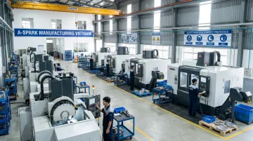
IATF 16949 certification is a baseline requirement for most automotive supply chains. A-SPARK Manufacturing holds this certification and runs an in-house CNC machining facility in Vietnam — 15 milling machines (3-, 4-, and 5-axis) and 30 CNC turning machines — producing powertrain parts, structural brackets, and heat sinks for automotive and EV customers.
Aerospace and Defense
Aerospace applications demand tight tolerances and exotic materials. CNC turning produces hydraulic fittings, spacers, and bushings. CNC milling creates turbine blades, structural ribs, weapon system components, and landing gear parts. Sandvik Coromant provides dedicated aeroengine component machining solutions covering turbine discs, casings, blisks, and structural components.
Medical Devices
Medical device manufacturing requires ISO 13485 compliance for quality management. CNC turning produces bone screws, dental implants, and surgical instrument handles. CNC milling creates surgical instrument housings, orthopedic implant components, and diagnostic equipment enclosures. PEEK is specifically noted for biocompatible medical implants and surgical instruments.
Oil & Gas
CNC machining supports oil & gas with valve bodies, pipe fittings, and downhole tool components in corrosion-resistant alloys. Turned components include valve stems, couplings, and fittings. Milled parts include manifold bodies and pump housings requiring complex internal passages.
Electronics, Industrial Equipment, and Renewable Energy
- Electronics: Heat sinks and enclosures (milling); precision connectors and terminals (turning)
- Industrial equipment: Gearbox components, structural frames, hydraulic fittings
- Renewable energy: Wind turbine shaft components (turning), solar mounting hardware and inverter housings (milling)
Each of these sectors places different demands on tolerances, materials, and certifications — which is why understanding the specific requirements of your industry is the starting point for any machining project.
Frequently Asked Questions
What are the 7 major parts of a milling machine?
The seven key structural and functional components are:
- Bed/base — foundation that absorbs vibrations and supports the entire machine
- Spindle — rotates and drives cutting tools at programmed speeds
- Worktable — holds and positions the workpiece along X/Y axes
- Column — vertical support structure connecting bed to spindle head
- Tool changer/magazine — stores and automatically exchanges cutting tools mid-operation
- CNC control panel/MCU — interprets G-code and directs all machine movements
- Drive system — servo motors with ball screws or linear drives executing precise axis movement
What is the difference between CNC turning and CNC milling?
In CNC turning the workpiece rotates while the cutting tool remains stationary, ideal for cylindrical parts. In CNC milling the cutting tool rotates while the workpiece is fixed, ideal for prismatic, flat, or complex-profile parts. Choosing between them comes down to part geometry — cylindrical forms go to turning, everything else typically goes to milling.
Can CNC turning produce non-cylindrical parts?
Yes. Modern turning centers with live tooling can add flats, cross-drilled holes, slots, and tapped holes in the same setup. These hybrid turn-mill operations eliminate secondary machining for roughly 60% of turned components that need non-cylindrical features.
What tolerances can CNC turning and milling achieve?
CNC turning typically holds tolerances of ±0.001" to ±0.005" with surface finishes down to 32 µin (Ra 0.8 µm). CNC milling typically holds ±0.004" (±0.1 mm) with 125 µin (Ra 3.2 µm) finishes under standard conditions. Both can achieve tighter specifications (down to ±0.0001") with optimized setups and tooling.
What materials can be used in CNC turning and milling?
Common compatible materials include aluminum, steel, stainless steel, brass, copper, titanium, and engineering plastics such as nylon, acetal (Delrin), polycarbonate, and PEEK. Material selection depends on the part's functional requirements, machinability, and end-use environment — harder materials require carbide or ceramic-coated tooling and may demand slower feed rates.
How do I decide whether my part should be turned or milled?
Use CNC turning for parts that are cylindrical, rotationally symmetric, or producible from bar stock. Use CNC milling for parts with flat faces, pockets, complex 3D profiles, or multi-plane features. For hybrid geometries, involve your manufacturing partner at the design stage — early DFM review prevents costly tooling changes and often reveals where turn-mill centers can consolidate operations.