Introduction
Sourcing metal components that hit exact design specs—without blowing lead times or budgets—is one of the most persistent challenges for engineering and procurement teams across automotive, aerospace, electronics, and renewable energy. Custom sheet metal fabrication addresses this directly, transforming flat metal sheets into finished components through cutting, forming, joining, and finishing operations tailored to specific application requirements.
The global sheet metal fabrication services market reached USD 22.32 billion in 2025, projected to grow to USD 34.72 billion by 2035—reflecting the critical role custom fabrication plays across industries. This guide walks through the full fabrication process—from material selection and cutting methods to forming, finishing, and supplier evaluation—so you can make informed decisions at every stage of your project.
Key Takeaways
- Custom sheet metal fabrication transforms flat sheets into precise components across six stages: design review, material selection, cutting, forming, assembly, and finishing
- Preferred when projects demand tight tolerances, design flexibility, and scalable production from prototype to mass manufacturing
- What determines quality: material choice, tooling precision, DFM review discipline, and fabricator capability
- Common pitfalls: skipping DFM review, over-tolerancing parts, and working with fabricators who lack certifications or full-process capability
What Is Custom Sheet Metal Fabrication?
Custom sheet metal fabrication shapes thin, flat metal sheets—measured in gauges—into engineered components using cutting, bending, forming, welding, and finishing operations tailored to specific design requirements. Sheet metal is defined as material under 0.25 inches thick; anything thicker is classified as plate.
The gauge system uses higher numbers for thinner materials, with thickness varying by material type. For example, 14-gauge steel measures 0.0747" while 14-gauge aluminum is 0.0641". Industrial fabrication typically works within the 7-gauge (0.1793") through 30-gauge (0.0120") range, with 14–20 gauge most common for enclosures, brackets, and panels.
Unlike standard off-the-shelf components, custom fabrication is designed around exact geometry, tolerances, material specifications, and application requirements — so parts meet precise assembly or performance criteria without compromise.
This matters most in applications where standard parts simply won't do:
- EV battery enclosures requiring specific thermal management properties
- Aerospace housings where weight reduction cannot sacrifice structural integrity
- Medical device enclosures subject to stringent hygienic standards
- Industrial panels demanding non-standard geometry or tight fit-up tolerances
Custom Fabrication vs. Metal Stamping
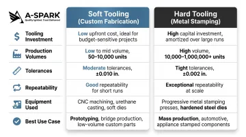
Custom sheet metal fabrication (soft tooling) and metal stamping (hard tooling) serve different production scenarios:
| Attribute | Soft Tooling (Fabrication) | Hard Tooling (Stamping) |
|---|---|---|
| Tooling investment | Standard tooling; no custom dies | Custom dies; single curved-bend tool: $13,000+ |
| Volumes | Prototypes through mid-volume production | High-volume production runs |
| Tolerances | +/-0.005" to +/-0.015" | +/-0.001" to +/-0.005" |
| Repeatability | Subject to slight variances from manual setups | Near-identical parts due to fixed die tooling |
| Equipment | Laser cutters, press brakes, punch presses | Mechanical and hydraulic presses (20-6,000 tons) |
| Best for | Design iteration, complex geometries, low-to-mid volumes | Uniform shallow-formed parts at high volumes |
Many assemblies use both methods strategically—custom fabrication for complex base components and stamping for high-volume fasteners or simple brackets.
Why Custom Sheet Metal Fabrication Is Used Across Industries
Custom fabrication is chosen when standard components cannot meet the dimensional, material, or performance requirements a project demands — and off-the-shelf parts simply won't cut it.
Market demand drivers: The broader sheet metal market reached USD 181.85 billion in 2024, forecast to reach USD 272.26 billion by 2030 at a 7.0% CAGR. Automotive and EV adoption (7.03% CAGR), aerospace expansion, and electronics miniaturization are all pushing that demand upward — sectors where standard parts consistently fall short.
Standard manufacturing falls short when projects demand:
- Aerospace brackets held to +/-0.005" hole-to-hole accuracy across multiple bends
- EV battery enclosures with integrated cooling channels and EMI shielding in a single assembly
- Material-specific performance — stainless steel for corrosion resistance, copper for conductivity, aluminum for weight reduction
- Prototype-to-production cycles without committing to expensive hard tooling upfront
These requirements appear consistently across the industries driving custom fabrication's growth.
Key vertical applications:
| Industry | Typical Components |
|---|---|
| Automotive & EV | Structural brackets, battery enclosures, heat shields |
| Aerospace & Defense | Avionics housings, aircraft structural components |
| Electronics | RF/EMI shielding, server rack enclosures, thermal management housings |
| Medical Devices | Surgical instrument trays, diagnostic equipment enclosures |
| Renewable Energy | Solar panel mounting systems, wind turbine component housings |
How the Custom Sheet Metal Fabrication Process Works: Step by Step
Custom sheet metal fabrication follows a defined production sequence where quality at each stage directly affects the final part's dimensional accuracy, structural integrity, and surface performance. Design decisions made upstream — tolerances, hole placement, bend radii — create compounding effects on every cutting, forming, and assembly step that follows.
Step 1: Design, Engineering Review & DFM
The process begins with engineering drawings or CAD files, followed by a Design for Manufacturability (DFM) review. Fabricators assess whether part geometry, tolerances, and material specifications can be efficiently produced. This step catches cost-inflating issues before tooling or cutting begins.
What DFM review identifies:
- Holes placed too close to bends (causing distortion)
- Over-specified tolerances that drive cost without improving function
- Material thickness incompatible with specified bend radii
- Features requiring secondary operations that could be eliminated through design modification
Late-stage design changes cost orders of magnitude more than early optimization. One automotive case study showed that tightening tolerances post-tooling added a 20% cost increase, while re-optimizing tolerance specifications in the design phase achieved a 15% cost reduction.
A-SPARK Manufacturing conducts on-site engineering review and rapid DFM analysis at this stage — catching manufacturability issues early, recommending material substitutions, and shortening development cycles for OEM clients before a single cut is made.
Step 2: Material Selection
Material choice is driven by functional requirements balanced against cost constraints:
Selection criteria:
- Aluminum offers strength-to-weight advantages for EV and aerospace components
- Stainless steel provides corrosion resistance for medical devices, food processing, and marine use
- Copper and brass suit electronics and heat exchangers where conductivity matters
- Cold-rolled steel remains the go-to for cost-sensitive industrial applications
Material gauge impact: Thickness determines minimum achievable hole sizes, bend radii, and realistic tolerances. Material thickness variation of +/-0.007" in 14-gauge steel propagates through every downstream operation, affecting final dimensional accuracy.
Step 3: Cutting
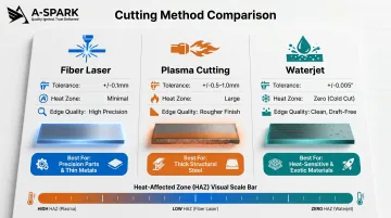
Primary cutting methods are selected based on material type, thickness, and required edge quality:
| Method | Tolerance | Heat-Affected Zone | Thickness Capacity | Edge Quality | Best For |
|---|---|---|---|---|---|
| Fiber Laser | +/-0.1 mm | Small: 0.1-0.5 mm | Up to 30 mm | High quality; minimal burr | Complex patterns, thin-to-medium materials |
| Plasma | +/-0.5 to 1.0 mm | Large: 1-3 mm | Up to ~2" mild steel | Rougher; may require grinding | Thicker materials, lower-cost applications |
| Waterjet | +/-0.005" (+/-0.13 mm) | None (cold process) | Any thickness | 100-125 RMS; clean, draft-free | Heat-sensitive materials, thick plate |
Method selection considerations:
- Laser cutting excels for stainless steel under 20 mm with complex geometry
- Plasma cutting offers speed advantages for thicker mild steel but produces rougher edges
- Waterjet cutting produces no thermal, physical, or chemical alterations, making it ideal for heat-treated metals where maintaining material properties is critical
Common error: Using plasma on thin stainless steel causes heat distortion, while laser cutting very thick plate is slower and more expensive than plasma or waterjet alternatives.
Step 4: Forming and Bending
Forming operations shape flat cut blanks into three-dimensional components:
Press brake bending uses punch and die tooling to create precise angle bends. Precision bending can achieve +/-0.005" tolerances, but requires strict controls: consistent material vendor, grain direction alignment, and pre-sorted pieces by thickness.
Realistic bending tolerances for production environments:
- Single-surface hole-to-hole: +/-0.005" to +/-0.010"
- Across four bends: +/-0.030" linear tolerance
- Angular tolerance: +/-0.5° to +/-2° per bend (stacking)
Why tolerance stacks: Material thickness variation of +/-0.006" produces up to 4 degrees of angular variation. This error compounds across multiple bends because material elongation changes with thickness, causing bend deduction to fluctuate by as much as 0.016" from part to part.
Other forming methods:
- Roll forming creates continuous profiles for channels and tubes
- Stamping uses hard tooling for high-volume uniform shapes with tightest repeatability
Step 5: Assembly and Joining
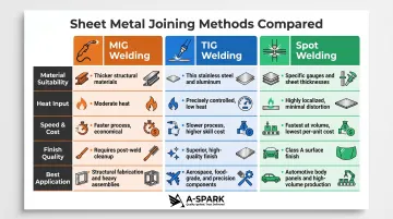
After forming, components are joined using methods selected based on structural requirements, material type, and accessibility:
| Method | Material Suitability | Heat Input / Distortion | Speed / Cost | Finish Quality | Application |
|---|---|---|---|---|---|
| MIG Welding | Thicker materials; structural steel | Moderate HAZ; higher distortion | Faster; economical | Requires cleanup | Structural components, watertight seals |
| TIG Welding | Thin materials; stainless, aluminum | Moderate but controlled | Slower; more expensive | High-quality, clean welds | Precision/cosmetic applications |
| Spot Welding | Specific thicknesses/geometries | Small, localized | Fastest; most economical at volume | Class A finish; not watertight | High-volume production |
Additional joining methods:
- Riveting where welding is inaccessible or dissimilar materials are joined
- Hardware insertion (PEM nuts, studs, standoffs) for threaded attachment points without tapping
- Adhesive bonding for joining dissimilar materials or vibration-sensitive assemblies
Step 6: Surface Treatment and Quality Inspection
Surface finishing protects against corrosion, improves aesthetics, and can add electrical insulation or conductivity:
Finishing options:
- Powder coating — Durable color finish; adds up to 0.002" buildup on features
- Anodizing — Aluminum corrosion protection with color options
- Plating (zinc, nickel, chrome) — Conductivity or aesthetic enhancement
- Passivation — Stainless steel corrosion resistance through chromium oxide layer enhancement
Critical design consideration: Powder coat buildup becomes problematic when it accrues on multiple edges of a feature (both sides of a hole), effectively reducing the opening. Designers should specify "all dimensions after finishing" to signal fabricators, and loosen hole tolerances accordingly.
Quality inspection: Final dimensional checks, visual inspection, and functional testing are conducted against engineering drawings. Documentation before release includes dimensional reports, process capability studies, and material certifications tied to each production lot.
Key Factors That Affect Precision and Outcome
Material Variability
Raw sheet metal has inherent thickness tolerances that propagate through every fabrication operation. Standard mill tolerance for 14-gauge cold-rolled steel is +/-0.007", meaning nominal 0.0747" material actually ranges from 0.0677" to 0.0817".
This variation causes:
- Bend deduction fluctuation (up to 0.016" per bend)
- Angular variation (up to 4 degrees)
- Cumulative dimensional error across multi-bend parts
Mitigation strategies:
- Source material from consistent vendors
- Pre-sort material by measured thickness before forming
- Account for material variance in tolerance stack-up calculations
Tooling Condition and Calibration
Worn dies, uncalibrated press brakes, and laser focus drift introduce dimensional error. Reputable fabricators maintain regular equipment calibration schedules and validate tooling wear against part specifications.
Warning signs of poor tooling management:
- Increasing dimensional variation within production runs
- Edge quality degradation (burrs, dross accumulation)
- Inconsistent bend angles across identical parts
Tolerance Specification Discipline
The "tighter isn't always better" principle: Excessively tight tolerances drive cost, inspection time, and rejection rates without improving function.
Functionally appropriate tolerances:
| Feature Type | Realistic Tolerance | Precision (with controls) |
|---|---|---|
| Edge to edge (single surface) | +/-0.005" | +/-0.003" |
| Hole to hole (single surface) | +/-0.005" | +/-0.003" |
| Bend to hole | +/-0.015" | +/-0.010" |
| Hole to hole (across 4 bends) | +/-0.030" | +/-0.020" |
ISO 2768-m provides general tolerance framework ranging from +/-0.10 mm (under 6 mm nominal) to +/-2.00 mm (2000-4000 mm nominal).
DFM review helps set functionally appropriate tolerances based on feature criticality rather than applying blanket tight tolerances that add cost without value.
Quality Assurance and Certification Standards
IATF 16949 is the most rigorous quality standard in the automotive supply chain. It extends ISO 9001:2015 with requirements for APQP (Advanced Product Quality Planning), PPAP (Production Part Approval Process), FMEA, MSA, and SPC — all focused on defect prevention and variation control.
Key certifications to verify when evaluating a fabrication partner:
- ISO 9001:2015 — baseline quality management system for consistent process control
- IATF 16949 — required for automotive supply chains; mandates statistical process control and documented approval workflows
- AS9100 — aerospace and defense applications
- ISO 13485 — medical device manufacturing
A-SPARK Manufacturing holds both ISO 9001:2015 and IATF 16949 certifications, covering full production traceability, PPAP documentation, and structured non-conformance resolution.
Supply Chain and Production Scalability
When cutting, forming, surface treatment, and assembly all happen under one roof, tolerance variation introduced at supplier handoffs disappears. For OEMs managing multi-component assemblies, this matters: dimensional error compounds across suppliers, and a single out-of-spec part can cascade into assembly failures.
Multi-region manufacturing presence reduces exposure to localized disruptions — capacity constraints, logistics delays, or regional shutdowns — while maintaining consistent quality standards across facilities.
Common Issues and Misconceptions
Cutting Methods Are Not Interchangeable
Method selection depends on material type, thickness, and geometry. Using plasma on thin stainless steel causes heat distortion. Laser cutting on very thick plate can be slower and more expensive than plasma or waterjet. Waterjet eliminates heat-affected zones but is significantly slower than laser for thin materials.
Cutting method assumptions are one of the most common sources of preventable rework — geometry decisions introduce a separate category of errors.
Holes Placed Too Close to Bends
The "4T rule" requires a minimum distance from hole to bend equal to at least four times the material thickness — violations cause distortion, cracking, or inaccurate hole placement. The precise minimums by feature type are:
| Feature | Minimum Distance from Bend |
|---|---|
| Holes under 25mm diameter | 2t + r |
| Slots | 4t + r |
(t = material thickness, r = bend radius)
Hole-to-bend violations are a frequent DFM flag. When caught late in the process, they add rework cost and delay delivery.
Surface Finishing Specified Too Late
Specifying finishing after tooling is complete causes dimensional surprises. Coating thickness affects final part dimensions and hardware fitment — details that must be locked in before tolerances are finalized. Powder coat curing at 300–400°F can cause slight distortion in thin-gauge aluminum or heat-treated metals.
Best practice: Include finishing specifications in the design package from the outset, with explicit callouts indicating whether dimensions apply before or after finishing.
Frequently Asked Questions
What is the process of sheet metal fabrication?
Sheet metal fabrication moves through six core stages: DFM analysis and design review, material selection, cutting (laser/plasma/waterjet), forming (press brake/roll forming), joining (welding/riveting/hardware insertion), and surface finishing (powder coating/anodizing/plating). Each stage is sequenced to meet required dimensional tolerances and surface quality standards.
What industries use metal fabrication?
Sheet metal fabrication serves most industries that need precision-engineered metal components, including:
- Automotive & EV (battery enclosures, structural parts)
- Aerospace & defense (avionics housings, brackets)
- Electronics (EMI shielding, thermal management)
- Medical devices, renewable energy, and industrial equipment
What metal will never rust?
No metal is completely rust-proof. Stainless steel, aluminum, and titanium offer the highest natural corrosion resistance — each forming a protective oxide layer. Surface treatments such as anodizing, powder coating, and passivation extend that protection further by creating additional barrier layers.
What is the 4T rule in sheet metal?
The 4T rule states that minimum distance between a hole and a bend should be at least four times the material thickness—to prevent distortion, cracking, or inaccurate hole placement during forming. More precisely, holes require 2t + r minimum distance (t = thickness, r = bend radius), while slots require 4t + r.
What is the difference between custom and standard sheet metal fabrication?
Standard fabrication produces off-the-shelf components to fixed, predefined specifications. Custom fabrication is engineered to client-specific drawings, tolerances, and material requirements — making it essential for complex assemblies where standard parts cannot meet the actual design.
What certifications should I look for in a sheet metal fabrication partner?
ISO 9001:2015 confirms a documented quality management system with continual improvement processes. For automotive supply chains, IATF 16949 is required — covering APQP, PPAP, FMEA, and SPC. For regulated industries, also look for ISO 13485 (medical devices) or AS9100 (aerospace).